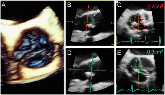
Figure 11.
Planimetry using 3D TOE. A 3D volume of the aortic valve is obtained (A). The volume can be manipulated to display orthogonal planes. Image (B) depicts a long-axis view, and the dotted red line depicts the plane from which a short-axis view (C) is then shown. This plane is aligned with the point of insertion of the valve cusps. In (D), the image has been manipulated, and the ‘plane of interest’ moved further into the aorta such that it now aligns with the valve tips (dotted green line). The short axis window obtained at the level of the dotted green line is displayed in image (E). Planimetry obtained in image (C) clearly overestimates aortic valve orifice area when compared to the result obtained by planimetry in image (E).

 This work is licensed under a