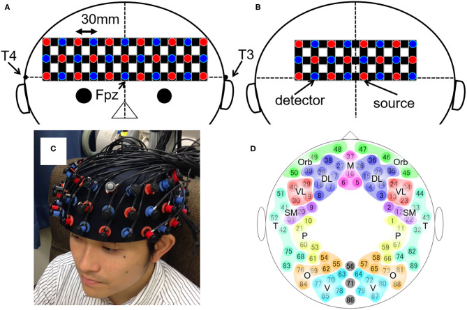
Figure 1.
The layout of the whole-head NIRS system and the 89 measuring points. (A,B) Schematic illustration of (A) the anterior and (B) the posterior shells of the whole-head NIRS arrangement. The red and blue circles depict the source and detector probes, respectively. The black horizontal line represents the planar surface defined by T3, Fpz, and T4 according to the international 10–20 system for electroencephalography. The black vertical line represents the midline. (C) The actual placement of the probes on the head. (D) Schematic illustration of the 89 measuring points and their categorization into 17 brain regions. DL, dorsolateral prefrontal cortex; M, medial prefrontal cortex; Orb, orbitofrontal cortex; VL, ventrolateral prefrontal cortex; SM, sensorimotor area; P, parietal lobe; T, temporal lobe; O, occipital lobe; V, visual area.

