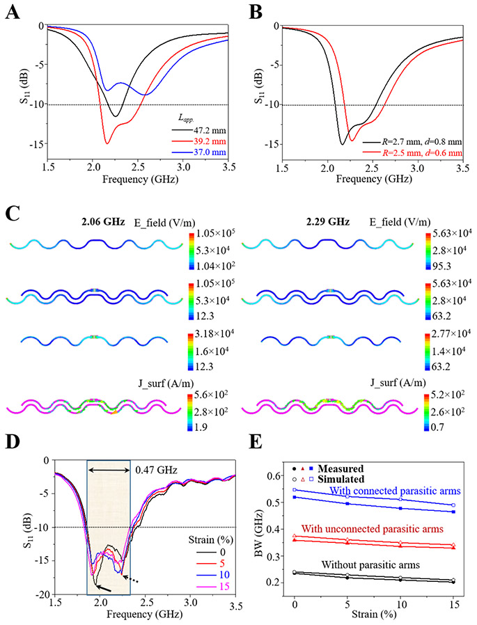
Figure 2. Design of the stretchable wideband antenna and its mechanical-electromagnetic properties.
(A) Influence of the relative length difference between driven and parasitic arms on the S11 curve of the antenna. The apparent length of driven arms (Lapp.) varies (i.e., 37.0, 39.2, and 45.1 mm), whereas the parasitic arms are fixed at a length of 47.2 mm. Bandwidth is defined as the frequency range with S11 values lower than −10 dB (corresponding to a standing wave ratio of ~2), as indicated by the dotted lines. (B) Influence of the uniform gap between the driven and parasitic arms as it reduces from 0.8 to 0.6 mm (while fixing the inner radius at 1.2 mm and changing the outer radius from 2.7 to 2.5 mm). (C) Simulated electric field (E_field) and surface current (J_surf) distribution of the “FS-Connected-I” (stretchable wideband) antenna at resonance at two resonance frequencies 2.06 and 2.29 GHz, respectively. The size of arrows in the surface current distribution also indicates the magnitude. (D) Measured S11 curves of the stretchable wideband antenna under a tensile strain up to 15%. The two arrows indicate the two resonance states. (E) Measured and simulated bandwidth of the stretchable antenna with connected or unconnected parasitic arms and without parasitic arms.

