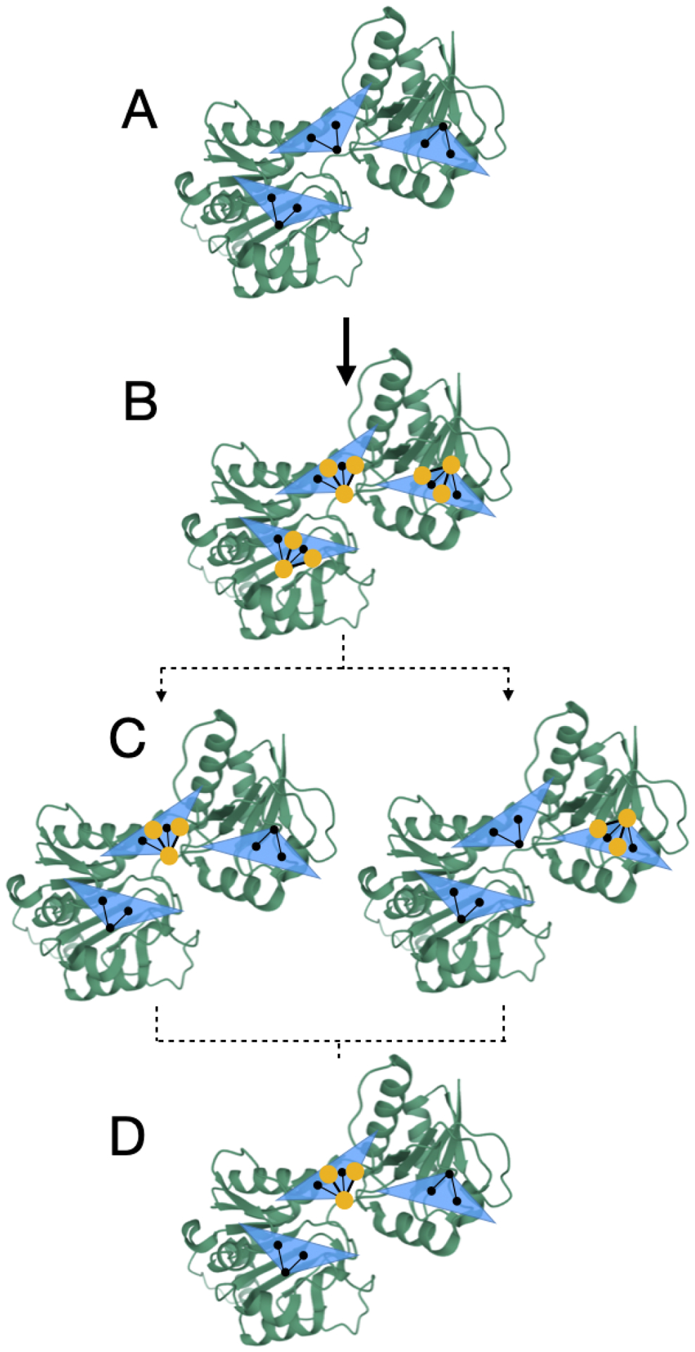
Figure 3: Rotations are handled deterministically during MolDarting.

We illustrate how we perform our rotational darting moves using a 2-dimensional rotational region as an example, with a single molecule that will be moved via MolDarting. The rotational regions are represented by the blue triangle, with the center of each rotational region (which was defined by some reference pose) represented by the three black circles connected by black lines, and the ligand in our simulations represented by the yellow circles connected by yellow lines. In this example, there are three total darts, each with an associated rotational region. (A) A representation of the three rotational regions used. (B) When a particle is within a rotational region the rotation matrix is calculated from the current positions to the reference positions. (C) When MolDarting, the rotation matrix calculated in (B) is applied to the reference positions of each other rotational region to determine the molecule’s new position. The dotted arrows refer to the two potential outcomes of the MolDarting move in which the ligand is darted to a new configuration. (D) One of the new reference regions are chosen randomly (with equal probability) to be MolDarted, resulting in a new configuration.
