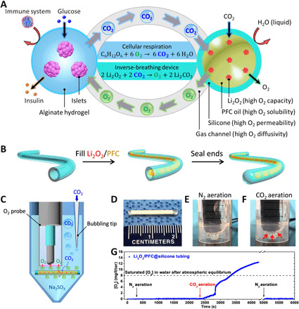
Fig. 1. An inverse-breathing system for encapsulated cells.

(A) A schematic representation of the inverse-breathing system: Islets were encapsulated in a semipermeable alginate hydrogel that permitted the transport of nutrients and the delivery of insulin but prevented the infiltration of immune effector cells; CO2 released from the cells was rapidly transported in the gas phase to PFC-encapsulated Li2O2 particulates, contained within a gas-permeable, liquid-impermeable silicone membrane, whereby CO2 was recycled into O2. (B) Fabrication steps for a test construct. (C) A schematic representing the CO2-responsive O2 generation confirmation test: A construct was submerged in Na2SO3-deoxygenating buffer and aerated with CO2; the CO2 diffused through the silicone tubing and reacted with the encapsulated Li2O2, leading to O2 bubble generation and accumulation on the construct’s surface; the O2 bubbles attached to the bottom of the O2 probe, diffused through the gas permeable membrane of the O2 probe, and were detected by the electrode. (D) A digital image of a test construct. (E and F) Digital images of the test assembly during (E) N2 aeration and (F) CO2 aeration (arrows indicate generated O2 bubbles). (G) O2 production over time measured by the submerged O2 probe near the device (arrows indicate aeration phase start times). Photo credits: (D to F) Long-Hai Wang, Cornell University.
