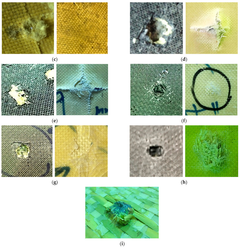
Figure 5.
The deformed plates after the ballistic test: (a) strike face (left) and back face (right) of the flat non-hybrid [KFRP40] plate (#1), sample 1, shoot 1; (b) path of the stopped bullet between KFRP layers in the flat non-hybrid [KFRP]40 plate (#1); (c) strike face (left) and back face (right) of the curved non-hybrid [KFRP40] plate (#2), sample 2, shoot 1; (d) strike face (left) and back face (right) of the flat hybrid [CFRP4/KFRP6]4 plate (#3), sample 1, shoot 1; (e) strike face (left) and back face (right) of the curved hybrid [CFRP4/KFRP6]4 plate (#4), sample 3, shoot 1; (f) strike face (left) and back face (right) of the flat hybrid [CFRP10/KFRP30] plate (#5), sample 1, shoot 1; (g) strike face (left) and back face (right) of the curved hybrid [CFRP10/KFRP30] plate (#6), sample 2, shoot 1; (h) strike face (left) and back face (right) of the flat [CFRP4/[DPRP2/KFRP10]3] plate (#7), sample 3, shoot 1; (i) stopped bullet inside the [CFRP4/[DPRP2/KFRP10]3] plate.


