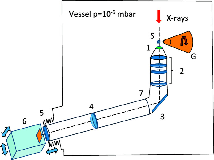
Figure 1.
A schematic drawing of the tomography system. 1 – scintillation screen, 2 – objective, 3 – mirror, 4 – relay lens, 5 – vacuum window, 6 – tomography camera, 7 – L-shaped tube. The system is residing inside of a vacuum vessel with pressure bellow 1.0 × 10⁻⁶ mbar. X-rays are impinging upon a protein sample (S) mounted on the goniometer (G).

