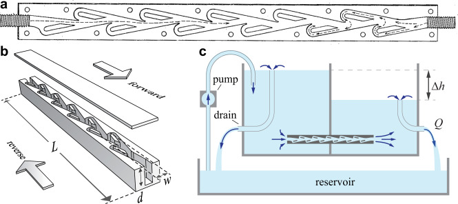
Fig. 1. Experimental tests of Tesla’s conduit under steady pressures.
a Schematic modified from Tesla’s patent10 showing a planform view of the `valvular conduit’. b Rendering of the conduit used in experiments. Upper and lower lids sandwich the internal geometry, which is digitized from Tesla’s design, laser-cut, and bonded. Relevant dimensions include total length L, average wetted width w, and depth d. c Schematic of the pressure chamber. Overflow mechanisms ensure fixed water levels that drive flow through the conduit, whose actual orientation is upright as shown in b. The height differential Δh is varied and volumetric flow rate Q measured for both forward and reverse directions.

