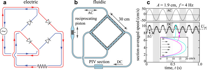
Fig. 5. Electronic AC-to-DC converter and an analogous fluidic pump.
a Electric circuit with four ideal diodes that converts alternating current source (AC, left branch) to direct current (DC, lower branch). Red and blue lines highlight the path and direction of current at different phases in the AC cycle. b Sectional view of an analogous fluidic circuit with four Tesla diodes and a pulsatile flow source. The experimental device employs a reciprocating piston of amplitude A and frequency f as an AC source in one branch, and the DC flow is measured in a second branch. c Section-averaged flow imposed in the AC branch (top) and measured in the DC branch (bottom) for A = 1.9 cm and f = 4 Hz. The mean flow rate UDC > 0 indicates successful AC-DC conversion or pumping. Inset: sample flow velocity profiles measured by PIV.

