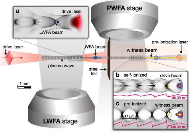
Fig. 1. Schematic overview of the experiment.

Two consecutive gas jets form the basis of an LWFA-driven PWFA. A high-intensity laser pulse (red) drives an LWFA in the first stage, generating a high peak-current electron beam (blue). The spent LWFA laser is reflected by a thin steel foil, whereas the electron beam propagates into the second stage, acting as the PWFA driver. In the PWFA stage, a witness beam (yellow) is accelerated. In addition, a counter-propagating low-power laser pulse can be applied for generating a pre-formed plasma channel in the PWFA stage prior to the drive beam arrival. a Illustration of a plasma wave driven by the high-intensity laser, with electron density in gray. b Plasma wave generated by the LWFA electron beam in the self-ionized PWFA regime. c Excited plasma wave in the pre-ionized PWFA regime. Images shown in a, b, c are obtained from simulations using the code OSIRIS. The purple line in b and c represents the longitudinal electric field on axis, considering only the interaction of the drive beam with the second gas jet.
