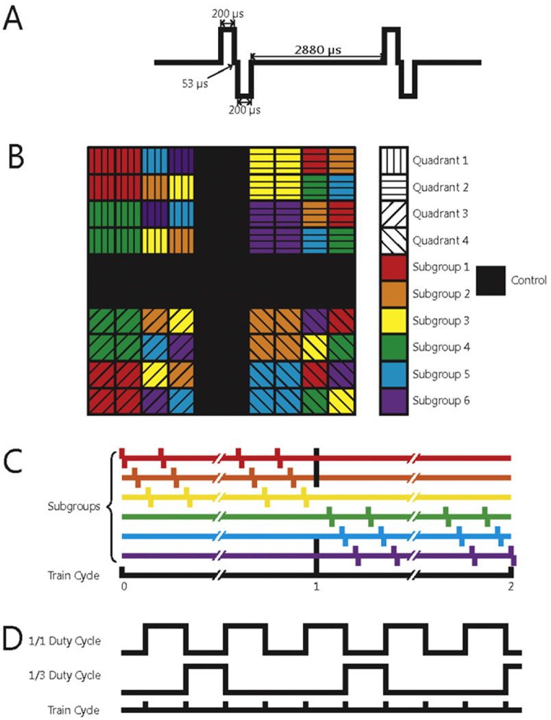
Figure 2.

(A) Schematic of two charge-balanced stimulation pulses at 300 Hz. (B) Electrode arrangement in each array. Each quadrant of electrodes was subjected to a different regime of stimulation. Black squares denote control electrodes. Arrays were divided into subgroups designed to control the amount of charge that was simultaneously delivered to the subject. Within a given quadrant, all subgroups were stimulated with the same stimulation parameters. (C) Different stimulation regimes were also interleaved to distribute the current as evenly over time as possible. (D) Interleaving of the 1/1 (50%) and 1/3 (25%) duty cycles.
