

Abstract
The bacterial flagellar motor can rotate in counter-clockwise (CCW) or clockwise (CW) senses, and transitions are controlled by phosphorylated form of the response regulator CheY (CheY-P). To dissect the mechanism underlying flagellar rotational switching, we use Borrelia burgdorferi as a model system to determine high-resolution in situ motor structures in cheX and cheY3 mutants, in which motors are locked in CCW or CW rotation. The structures showed that CheY3-P interacts directly with a switch protein FliM, inducing a major remodeling of another switch protein, FliG2, and altering its interaction with the torque generator. Our findings lead to a model in which the torque generator rotates in response to an inward flow of H+ driven by the proton motive force and CheY3-P medicated conformational changes of FliG2 allow the switch complex to interact with opposite sides of the rotating torque generator, facilitating rotational switching.
Keywords: rotary motor, switch complex, supramolecular complex, FliG, CheY
Introduction
The bacterial flagellum is a remarkable nanomachine that can rotate in both the counter-clockwise (CCW) and clockwise (CW) directions and can switch rapidly between the two rotational states1–4. Regulation of rotational direction is key for bacterial chemotaxis, a behavior that enables the cells to move toward attractants or away from repellents5,6. In externally flagellated bacteria, such as Escherichia coli and Salmonella enterica serovar Typhimurium, CCW rotation of the flagella coalesces the external helical flagellar filaments into a bundle that produces smooth swimming (a run), and CW rotation disrupts the bundle and reorients the cell (a tumble)(Extended Data Fig. 1a, b)1. A sophisticated chemotaxis signaling system allows the cell to sense stimuli and transmit this information via a phosphorylated form of the response regulator CheY to regulate the direction of rotation5,6. Although it is well known that lower levels of CheY-P promote CCW rotation and higher levels promote CW rotation, the exact mechanism of CheY-P induced rotational switching is unknown1,3,4,7. Intriguingly, recent data suggest that flagellar switch proteins are highly dynamic and that the number of subunits vary significantly in E. coli and S. enterica motors rotating CCW and CW8,9. However, it is unclear how the flagella could accommodate such large changes while still maintaining rapid rotation and switching.
Spirochetes are a unique group of bacteria with distinct morphology and motility10,11. Spirochetes possess multiple internal periplasmic flagella that are attached near each cell pole. These flagella are located between the outer membrane sheath and the cell cylinder, and their rotation causes the entire cell body to rotate (Extended Data Fig. 1e, f)10. Spirochetes run when the anterior flagella rotate CCW and the posterior flagella rotate CW12,13. When the flagella at both poles rotate in the same direction, the spirochetes flex in place and fail to move translationally12,13. To swim toward an attractant, spirochetes have evolved a complex chemotaxis and motility system to coordinate rotation of the flagella at the two cell poles10,14. CheY3 is a key response regulator that is essential for chemotaxis in B. burgdorferi; ΔcheY3 mutant cells are non-chemotactic and constantly run13. CheX is the CheY-P phosphatase identified in B. burgdorferi15. A ΔcheX mutant constantly flexes and is unable to run in vitro15.
The rotary motor is the most intricate part of the flagellum; it is responsible for flagellar assembly, rotation and directional switching. Whereas details of the motor structures vary among species, the core components, which are the products of billions of years of evolution, are highly conserved16,17. The membrane-bound stator and the switch complex (also called C-ring) are directly responsible for flagellar rotation and switching. The stator complex is the torque generator powered by ion flux across the membrane. It is composed of two transmembrane proteins, called MotA and MotB in E. coli and B. burgdorferi18,19. MotA has a large cytoplasmic domain, which contains several conserved charged residues that are critical for the interaction with the switch complex20. MotB has a large periplasmic domain that is believed to bind to the peptidoglycan layer21,22. The switch complex is comprised of three proteins (FliG, FliM, and FliN) that assemble to form the characteristic C-ring at the cytoplasmic side of the motor. FliG is the protein most directly involved in interacting with the stator to generate torque23. In B. burgdorferi, which has two FliG proteins, FliG2 is present in the C-ring24 and plays a similar role as its counterpart in other bacteria. FliG1 is located at one cell pole; it remains unknown if it is a part of the C-ring24. FliM and FliN are extensively involved in switching the direction of the motor3.
To reveal the molecular architectures of the flagellar motor in CCW and CW rotations and the mechanism underlying the rotational switching, we deployed cryo-electron tomography (cryo-ET) to visualize the motors in two B. burgdorferi mutants ΔcheX and ΔcheY3 in which the flagella are locked in CCW and/or CW rotation, respectively. The resulting in situ structures of the stator complex and switch complex enable us to uncover a significant conformational change in FliG2 upon binding of CheY3-P to FliM. Importantly, our data suggest a model in which the stator complexes rotate in response to proton flow and interact with FliG2 that are in radically different conformations to drive CW and CCW rotation, respectively.
Results
In situ structure of the flagellar motor in constantly flexing ΔcheX cells
Recent in situ structural analysis of the wild-type (WT) and ΔmotB flagellar motors in B. burgdorferi demonstrates the utility of combining cryo-ET and genetic approaches for understanding the structure and function of the intact B. burgdorferi flagellar motor19. In an unsynchronized pool of WT cells, the motors constantly change their rotational senses to drive the spirochetal motility. Therefore, it is challenging to sort out the WT motors into distinct CW or CCW conformations. To overcome this problem, we analyzed the flagellar motors in ΔcheX mutant cells which continuously flex and unable to run in vitro15 (Supplementary Video 1). Due to high levels of CheY3-P in the ΔcheX cells15, the motors in both cell tips are expected to be locked in CW rotation. Another advantage of analyzing the motors of these cells is that due to high levels of CheY3-P it may be possible to visualize the switch complex when it is occupied by this signaling protein.
To determine the in situ flagellar motor structure by cryo-ET and subtomogram averaging, we analyzed 1,056 flagellar motors from 246 tomograms of ΔcheX cell poles (Extended Data Fig. 2a, Table 1). The averaged structure reveals the core components of the flagellar motor – such as the stator, C-ring, export apparatus, and spirochete-specific collar19 (Fig. 1a). A B. burgdorferi flagellar motor has 16 stator complexes, which form a large ring with 62 nm in diameter (Fig. 1a, b). Each stator complex contains a small, 8 nm bell-shaped cylinder across the cytoplasmic membrane (Fig. 1a, b). The improved structure of the C-ring, obtained after focused refinement (Fig. 1c and Extended Data Fig. 2e) shows 46-fold symmetry, consistent with that observed in the WT flagellar motors19.
Table 1.
Strains and cryo-ET data used for this study.
| ΔcheX | ΔcheY3 | cheX::cheY3-GFP | |
|---|---|---|---|
| Reference | 15 | 30 | This work |
| Motility phenotype | Constantly flexing | Constantly running | Constantly flexing |
| Pixel size (Å) | 2.747 | 2.747 | 2.245 |
| Defocus (μm) | 2 to 4 | 2 to 4 | 2 to 4 |
| Number of tomograms | 246 | 301 | 188 |
| Class-1: 939 | |||
| Number of motors | 1,065 | Class-2: 1,148 | 1250 |
| Number of subtomograms for stator-rotor refinement | Class-1: 14,066 | ||
| 12,925 | Class-2: 13,240 | 9,540 | |
| Resolution of refined stator-rotor region (FSC=0.5) | Class-1: ~19 Å | -- | |
| ~18 Å | Class-2: ~18 Å |
Figure 1. Structure of the flagellar motor in constantly flexing ΔcheX cells.
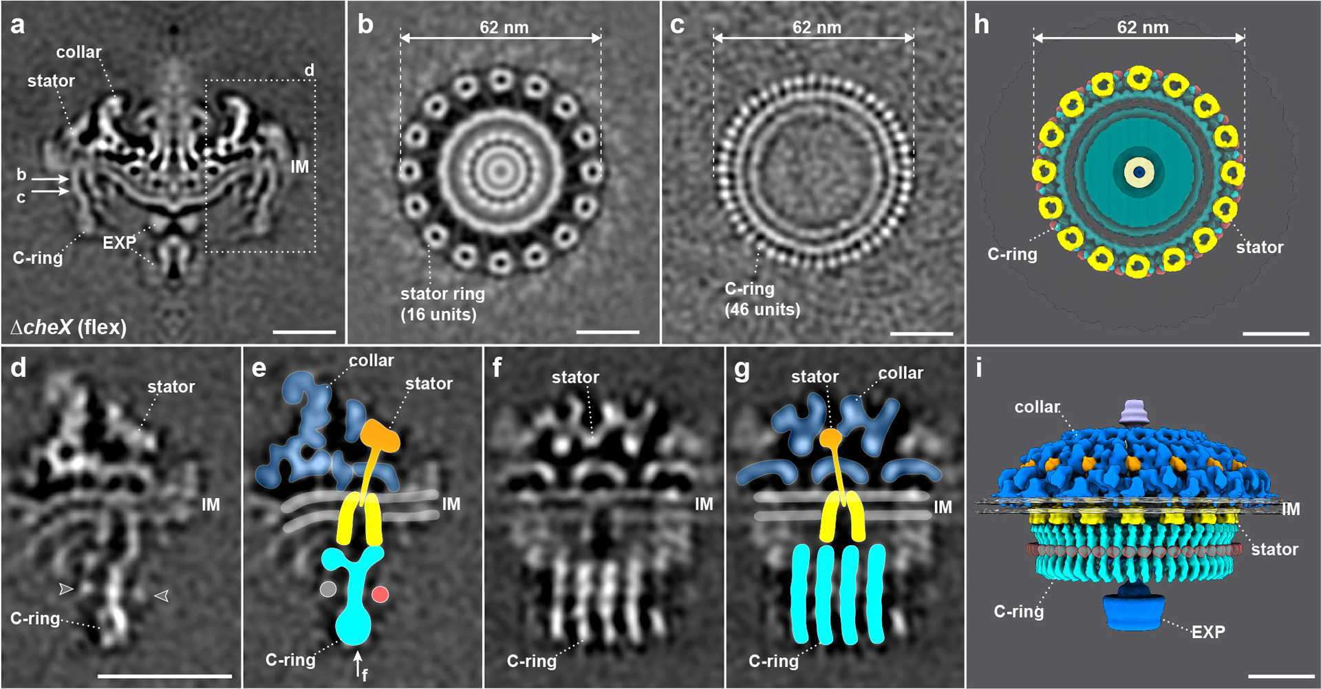
(a) A medial cross-section of the in situ flagellar motor structure in ΔcheX determined by subtomogram averaging. The collar, stator, C-ring and export apparatus (EXP) are clearly visible in the cryo-ET map. (b) A perpendicular cross-section of the flagellar motor structure showing the stator ring. (c) The C-ring structure after focused alignment showing 46-fold symmetric features. (d-g) Stator-rotor interaction region (dash framed in panel a) after focused alignment. The arrowheads in (d) pointed out the unidentified densities associated with the C-ring. (e, g) The structures shown in (d and f) superimposed with the corresponding models in two different views. The unidentified densities associated with the C-ring were highlighted with grey and red circles in (e). (h) A top view of the stator ring on the top of the C-ring. (i) A side view of the flagellar motor structure in 3D. Scale bars, 20 nm.
To further resolve detailed interaction between the C-ring and the stator complex, we applied symmetry expansion and utilized focused classification and alignment of the stator-rotor interaction region (dash framed region in Fig. 1a). The transmembrane and cytoplasmic portions of the stator complex have a bell-shaped structure embedded in the cytoplasmic membrane (Fig. 1d–g, Supplementary Video 2). It is 9 nm in height and 8 nm in diameter, which are similar to the dimensions of the purified stator complexes25,26 and MotA complex from Aquafex aeolicus27 (Extended Data Fig. 3). The periplasmic domain of the stator complex is inserted into the collar (Fig. 1d–g). It is ~9 nm long, and the top portion of its density corresponds well to the crystal structure of the S. enterica MotB periplasmic domain28 (Extended Data Fig. 3).
The C-ring exhibits a “Y” shape in the refined structure (Fig. 1d, e), which is similar to the previously reported in vitro C-ring structure in S. enterica29. However, the bottom portion of the C-ring forms a spiral in which adjacent subunits are connected to one another. The top portion of the C-ring interacts with the periphery of the stator cytoplasmic region. By assembling the collar, stator complexes, and C-ring together, we revealed a complex architecture of the CW-rotating flagellar motor with unprecedented details (Fig. 1h, i).
CheY3-P binds to the FliM protein of the C-ring
To characterize CheY3-P and its interaction with the ΔcheX motor, we replaced the cheX-cheY3 genes with cheY3-gfp, generating a cheX::cheY3-GFP mutant (Extended Data Fig. 4). Like ΔcheX, the GFP-labeled mutant constantly flexes. In addition, the mutant cells have fluorescent puncta at both cell poles (Fig. 2a), indicating that CheY3-P co-localizes with the flagellar motors. To confirm CheY3-P binding on the switch complex, we co-expressed His-CheY3 and FliM-FLAG in E. coli and affinity purified His-CheY3 and bound proteins by Ni-NTA binding in the presence or absence of acetyl phosphate (final concentration 40 mM). The purified products were examined using Western blots probed against anti-His or anti-FLAG antibodies. The His-CheY3* protein, in which Asp79 was converted to Ala, was used as a control, as it cannot be phosphorylated. In the presence of acetyl phosphate, FliM-FLAG co-purified with His-CheY3, but not with His-CheY3* (Fig. 2e, Extended Data Fig. 4b, c). In the absence of acetyl phosphate, and therefore at low levels of CheY3-P, only a small amount of FliM-FLAG co-purified with His-CheY3. In contrast to FliM, no FliN-FLAG co-purified with His-CheY3, even in the presence of acetyl phosphate (Fig. 2f). These results indicate that CheY3 binds to FliM in a phosphorylation-dependent manner.
Figure 2. CheY3-P binding to the flagellar motor.

(a) Fluorescence image of cheX::cheY3-GFP cells showing that GFP-tagged CheY3 proteins are polarly localized. (b) A medial cross-section of the flagellar motor structure in cheX::cheY3-GFP cells. (c) A refined structure of the stator-rotor interface (dash framed in panel b) in cheX::cheY3-GFP. Extra density (green arrow) is associated with the C-ring. (d) A cartoon model is superimposed onto the structure shown in panel c. The GFP density (green arrow indicated in panel c and green color highlighted in d) is located outside the C-ring. (e, f) Ni-NTA affinity purifications using the poly-histidine modified proteins HisCheY3 or HisCheY3* (CheY3D79A) to pull down FLAG-tagged FliM (FliM-FLAG) and FLAG-tagged FliN (FliN-FLAG), respectively. FliM-FLAG was co-purified with HisCheY3, but not with HisCheY3*, and more FliM-FLAG protein was co-purified with HisCheY3 in the presence of acetyl phosphate (e). There was no FliN-FLAG co-purified with HisCheY3/CheY3* (f). These results indicate that CheY3 binds to FliM protein in a phosphorylation-dependent manner. Scale bars, 10 μm in panel a, 20 nm in panel b.
To resolve the CheY3-P densities on the switch complex, we determined in situ structure of the motors in the cheX::cheY3-GFP mutant by cryo-ET and subtomogram averaging. Compared to the motor structure in the ΔcheX mutant, the motor structure in cheX::cheY3-GFP cells has an extra ring, likely contributed by GFP fused to CheY3 (green arrowhead in Fig. 2c). Together with the above biochemical data, we conclude that CheY3-P interacts with the FliM protein on the exterior side of the C-ring (Fig. 2c, d).
Distinct conformations of the switch complex in the absence of CheY3-P
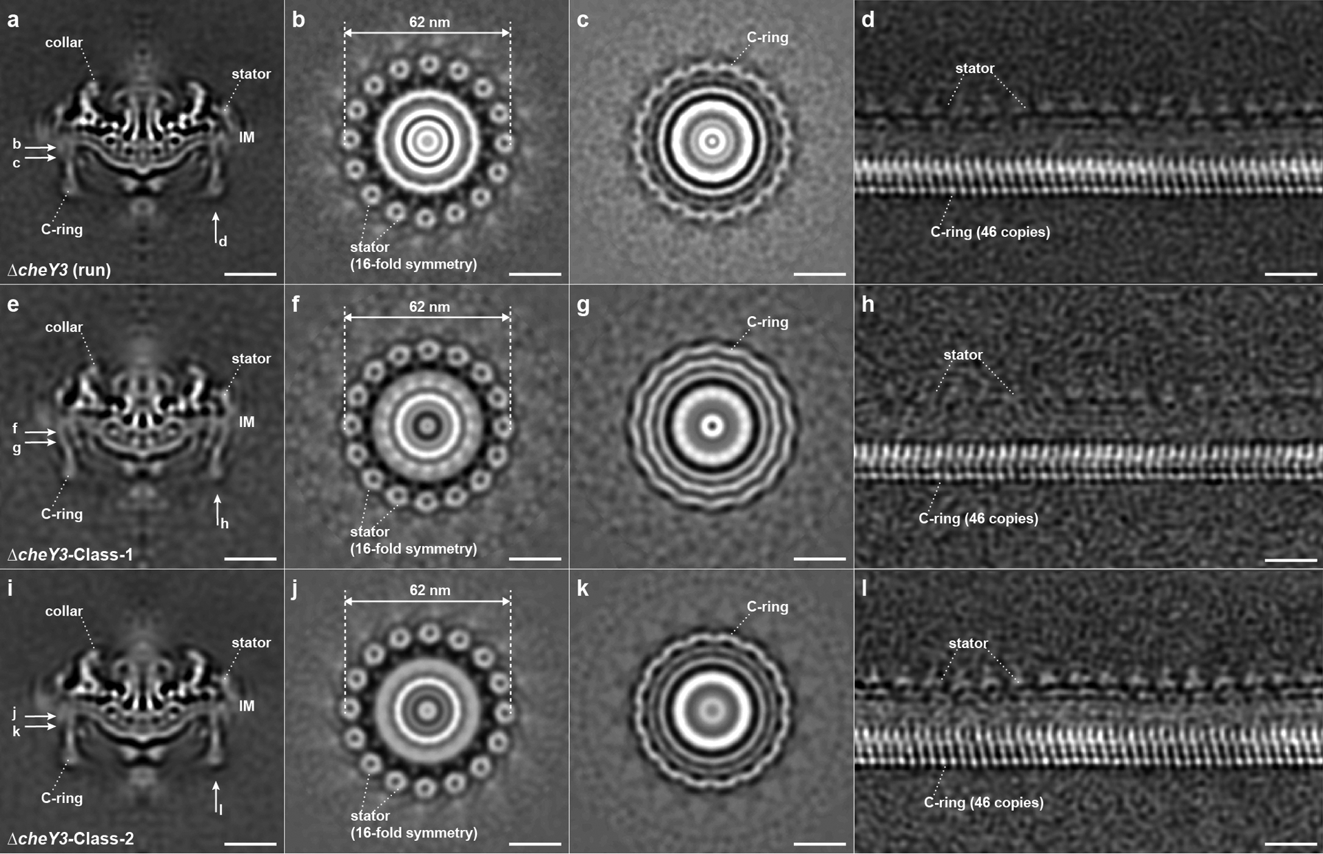
To compare the switch complex bound by CheY3-P with that in the absence of CheY3-P, we analyzed the motor structures in ΔcheY3 mutant cells, which continuously run and cannot reverse30 (Table 1, Extended Data Fig. 2b, Supplementary Video 3). The overall in situ motor structure in the ΔcheY3 mutant (Extended Data Fig. 5a, b) is quite similar to the averaged structure in the ΔcheX motor (Fig. 1a, b). Importantly, the stator ring is almost identical with 62nm in diameter. However, focused classification and alignment of the C-ring in the ΔcheY3 motors revealed two distinct conformations of the C-ring: ΔcheY3-Class-1 (Fig. 3a–e, Extended Data Fig. 5e–h, Supplementary Video 4, ~45% of the whole ΔcheY3 data set) and ΔcheY3-Class-2 (Fig. 3f–j, Extended Data Fig. 5i–l, Supplementary Video 5, ~55% of the whole ΔcheY3 data set), although they share the same 46-fold symmetry and exhibit a “Y” shape structure. The C-ring conformation of ΔcheY3-Class-1 motors (Fig. 3a–e, Extended Data Fig. 5h) is similar to that in the ΔcheX motor (Fig. 1d–g, Extended Data Fig. 2e), while the CheY3-P density is absent. In contrast, the C-ring in ΔcheY3-Class-2 (Fig. 3f–j, Extended Data Fig. 5i) is twisted in a different direction compared to that in ΔcheY3-Class-1 (Fig. 3a–e, Extended Data Fig. 5h) or the ΔcheX motor (Fig. 1d–g, Extended Data Fig. 2e), resulting in different interactions between the stator and the C-ring. Specifically, the top portion of the C-ring in the ΔcheY3-Class-1 motor interacts with the outer part of the stator complex (Fig. 3a, b), which is the same as in the ΔcheX motor (Fig. 1d, e). In contrast, the top portion of the C-ring in the ΔcheY3-Class-2 motor interacts with the inner part of the stator complex (Fig. 3f, g). Therefore, our results suggest that the flagellar rotational direction is correlated with distinct stator-rotor interactions. As the ΔcheY3 cells run constantly, we hypothesize that the ΔcheY3-Class-1 motors rotate CW near one pole, whereas the ΔcheY3-Class-2 motors rotate CCW near another pole. To test the model, we analyzed the motor structures at both poles in several ΔcheY3 cells. The refined C-ring structures from each cell pole were compared with those of ΔcheY3-Class-1 motors and ΔcheY3-Class-2 motors, respectively (Extended Data Fig. 6). Our data are consistent with the model in which the motors near one pole indeed rotate CCW, while the motors near another pole in the same cell rotate CW12,13.
Figure 3. Stator-rotor interactions in constantly running ΔcheY3 cells.

Two distinct conformations of the C-ring are observed in ΔcheY3 cells. (a-e) Detailed motor conformation in the ΔcheY3-Class-1 with the same views as shown in Fig.1d–g, i. (f-j) Detailed motor structures in the ΔcheY3-Class-2. The C-ring appears different in two class averages. In Class-1, the C-ring interacts with the outer part of the stator; while in Class-2, the C-ring interacts with the inner part of the stator. (e, j) 3D surface views of the ΔcheY3-Class-1 and ΔcheY3-Class-2 flagellar motors. Note that the C-ring has two distinct conformations, enabling two different interactions with the stator complexes. Scale bar, 10 nm.
CheY3-P binding triggers major remodeling of FliG2
The switch complexes seen in the ΔcheY3-Class-2 motor represent the conformation associated with the CCW rotational state (Fig. 4a–d), while those in the ΔcheX motor is locked in the CW rotational state because of CheY3-P binding. To understand molecular details of the distinct C-ring conformations in the CW and CCW motors, we modeled the switch complex in the absence and presence of CheY3-P (see Methods). The resulting C-ring models fit well into our density maps (Fig. 4b, f). FliG2 forms the “V” shape at the top of the C-ring. It interacts with the MS-ring via the N-terminal domain (FliG2N), and the stator complex via the C-terminal domain (FliG2C). The middle domain of FliG2 (FliG2M) interacts with the middle domain of FliM (FliMM), forming the stalk of the C-ring subunit. The C-terminal domain of FliM (FliMC) forms a heterodimer with FliN. A spiral is created at the base of the C-ring by alternating FliMC-FliN heterodimers and FliN-FliN homodimers (Fig. 4c, d), in which FliG2:FliM:FliN exist in a 1:1:3 stoichiometry as proposed previously31,32. When CheY3-P binds, the N-terminal domain of FliM (FliMN) interacts with CheY3-P, and this interaction results in an ~27° tilt of the FliMM (Extended Data Fig. 7). Importantly, although the spiral ring structure at the base of the C-ring remains almost the same, FliG2 undergoes a major remodeling in the ΔcheX motor (Fig. 4e, f) compared to that in ΔcheY3-Class-2 motor (Fig. 4a, b). The conformational change in FliG2 significantly enlarges the FliG2 ring from 55 nm to 62 nm, allowing FliG2 to interact with distinct parts of the stator ring (Fig. 4c, g, Extended Data Fig. 8).
Figure 4. Molecular architectures of the flagellar motors without and with CheY3-P.

(a) A medial cross-section of the flagellar motor structure without CheY3-P. (b) A pseudoatomic model of the C-ring unit shown in panel a. FliM and FliN have a stoichiometry of 1:3, and the FliMC together with three FliN units form a spiral at the base of the C-ring. (c) Interactions between the bell-shaped stator complex and the C-ring. The charged residues (Lys275, Arg292, Glu299, and Asp300 in red) in FliG2C interact with inner part of the stator complex. (d) A different view of five C-ring units connected at the based on the C-ring. (e) A medial cross-section of the flagellar motor structure in the presence of CheY3-P. (f) A pseudoatomic model of the C-ring unit with CheY3-P binding on the FliMN. (g) The charged residues (Lys275, Arg292, Glu299, and Asp300 in red) in FliG2C interact with outer part of the stator complex. (h) A different view of four C-ring units are occupied by four CheY3-P proteins.
Discussion
The stator complex is known to be highly dynamic in many bacterial species28,33. As a result, it has been very challenging to visualize the intact stator complex particularly in a functional motor16,17,19. Here, we used cryo-ET and sub-tomogram averaging to visualize the intact stator complexes in periplasmic flagella at unprecedented resolution. Sixteen stator complexes form a ring 62 nm in diameter. Each stator complex is composed of a bell-shaped structure embedded in the cytoplasmic membrane and a periplasmic domain inserted into the collar. The overall size of the stator complex is ~8 nm in diameter and ~18 nm in length. Importantly, the periplasmic domain and the bell-shaped structure match well with near-atomic structures of purified sub-complexes of the stator, respectively, suggesting that MotB forms the extended conformation after the stator complex is incorporated into a functional motor and MotA forms the bell-shaped structure across the cytoplasmic membrane. These findings are of particular importance, because they provide structural basis to understand how the stator complex interacts with the switch complex at the molecular level.
Our data suggested that the C-ring in B. burgdorferi motor consists of FliG2, FliM, and FliN (1:1:3) proteins. In each C-ring subunit, one FliM and three FliN proteins form the base, and one FliG2 stacks on FliM. Flexibility of the linker between the FliG2MC domains34–36 allows a large rearrangement of FliG2 during directional switching. In CW rotation, FliG2C interacts with the outer part of the stator ring, while during CCW rotation it interacts with the inner part of the stator ring. This association suggests that the outer part of stator cytoplasmic region drives the C-ring CW, while the inner part drives the C-ring CCW. This result is consistent with a model that the inward flow of protons drives the unidirectional rotation of the MotA portion of the stator. Based on these predictions, we propose a model for the generation of flagellar rotation and for the switching of rotational directions (Fig. 5, Supplementary Video 6). When protons flow inward through the stator ion channel, we postulate that the cytoplasmic region of the stator rotates CW (viewing from MotB through the membrane to MotA). In the default state (without CheY3-P) FliG2 interacts with the inner part of the stator cytoplasmic region and the C-ring rotates CCW (Fig. 5a, b). When CheY3-P binds to FliM from the exterior side of the C-ring (Fig. 5f, g), FliG2 undergoes a major remodeling to interact with the outer part of the stator (Fig. 5f, g). The interaction with the CW-rotating stator would then drive CW rotation of the C-ring (Fig. 5e). Given that the C-ring and stator are evolutionarily conserved, this molecular mechanism for flagellar rotational switching may be utilized, with some modifications, across a wide spectrum of bacterial species.
Figure 5. Model for the mechanism of rotational switching.

(a, b) Interactions of the stator with FliG2 in the C-ring during CCW rotation. In the default state when there is no bound CheY3-P, the FliG2 proteins interact with the inner part of the stator complex (colored in yellow). With the influx of protons through the stator channel, the cytoplasmic subunits of each stator complex spins CW. Therefore, the C-ring (blue) is induced to spin CCW. (c) A zoomed-in view of the interaction between the C-ring and the stator complex. (d) A perpendicular view shows that four C-ring units are connected by FliM/FliN interactions. (e, f) CheY3-P induced conformational changes in the C-ring result in altered interactions between the stator and C-ring, thereby causing the switch to CW rotation. When CheY3-P binds to FliM on the exterior surface of the C-ring, its binding triggers the shift (g) and tilt (h) of FliG2 so that FliG2C interacts with the outer part of the cytoplasmic domain of the stator complex (g). Because the cytoplasmic domain of the stator always spins CW, the C-ring is induced to spin CW (e). During the rotational switch, the spiral ring structure formed by FliM and FliN acts as a base to hold the C-ring structure together (d, h).
Many challenges remain to test this model. The most obvious one is to directly demonstrate that the cytoplasmic domains of the stator units actually rotate. Recent studies showed that cytoplasmic domain of the stator complex form a pentamer and may rotate in presence of the proton motive force25,26. Each stator unit contains a central MotB dimer and five peripheral MotA subunits. MotB is stationary; in B. burgdorferi it is embedded in the collar and firmly attached to the peptidoglycan of the cell wall. The critical conserved Asp residue required for proton conduction is on the single transmembrane helix of MotB17. The model predicts that the MotA subunits rotate around MotB in a manner that is coupled to the inward flow of protons, resulting in sequential interactions of the MotA subunits with consecutive FliG2 units in the C-ring (Fig. 5).
Due to its unique morphology, spirochete has evolved a complicated strategy to control motility10,11. In the constantly flexing ΔcheX cells, flagella in both cell poles have the same CW conformation. In contrast, we found two distinct conformations of the switch complex in the constantly running ΔcheY3 cells, supporting the notion13 that they are in CW and CCW rotational states to keep the cell running (Extended Data Fig. 9). However, it is still not clear how the spirochete produces asymmetric flagellar rotation in the complete absence of CheY3.
Comparison of the CW motor in ΔcheX cells with the CCW motor in ΔcheY3 cells provides direct evidence for a significant conformational change in the C-ring caused by CheY3-P binding to FliM. The diameter of the FliG2 ring expands from 55 nm to 62 nm upon binding of CheY3-P, whereas the diameter of the bottom portion of the C-ring remains similar (Extended Data Fig. 8). Importantly, the number of the C-ring subunits in both CCW and CW rotations remains unchanged. Our data is different from the reports in which there are more C-ring subunits in the E. coli and S. enterica motors rotating in CCW than those in CW rotation8,9. Further study will be required to better understand the differences and the conserved mechanism underlying the flagellar rotational switching.
In summary, we determined the structures of CW- and CCW-rotating flagellar motors in B. burgdorferi by cryo-ET and subtomogram averaging. We demonstrated that the flagellar switch complexes undergo substantial remodeling to form distinct interactions with the stator complexes during the rotational switching, analogous to throwing an automobile transmission into reverse. We propose a novel model for the generation of torque and the switching of rotational direction. A proton flux through the stator causes the bell-shaped MotA cytoplasmic region to rotate CW (view from the hook to the C-ring). Interactions with the outer part of the stator cytoplasmic region cause the C-ring to rotate CW, and interactions with the inner part of the stator cytoplasmic region cause the C-ring to rotate CCW. Control of the direction of flagellar rotation consists of aligning the interaction sites of the stator and the switch complex properly through conformational changes in FliG2 to achieve the desired direction of flagellar rotation.
Methods
Bacterial strains and growth conditions.
A high-passage B. burgdorferi sensu stricto strain B31A (WT) and its isogenic mutants were grown in Barbour-Stoenner-Kelly II (BSK-II) liquid medium or on semisolid agar plates at 34°C in the presence of 3.4% carbon dioxide as previously described37,38.
Escherichia coli TOP10 strain (Invitrogen, Carlsbad, CA, USA) was used for DNA cloning and plasmid amplifications. BL21 strains transformed with GroEL-GroES chaperones (Takara Bio USA) were used for recombinant protein preparations. E. coli strains were cultured in lysogeny broth (LB) supplemented with appropriate antibiotics as needed. The ΔcheX and ΔcheY3 mutants of B. burgdorferi were constructed and characterized as previously described39,40.
Inactivation of cheX using cheY3-gfp.
The vectors for in frame replacing cheX-cheY3 with cheY3-gfp were constructed by using a PCR-based fusion method as previously described40. Briefly, the PCR primers (containing complementary overlaps to downstream fragment) were designed immediately flanking the cheX-cheY3 genes, to generate approximate 1-kb products upstream and downstream of the coding sequences (Extended Data Fig. 10). The primers for the flgB promoter, cheY3, gfp and streptomycin resistance cassette (str) were designed. Initial PCR amplifications for each of individual fragments (i.e., 5’- and 3’-flanking DNA of cheX-cheY3, flgB promoter, cheY3, gfp, and str) were performed, followed by a fusion PCR connecting all the fragments together, generating the constructs of cheY3-gfp::str (Extended Data Fig. 4). The resultant constructs were transformed into competent B31A cells by electroporation to delete cheX-cheY3 genes. The resultant mutant clones were confirmed by PCR and western blots using antibodies against GFP, CheY3 and CheX, respectively.
Light and fluorescence Microscopy.
Fluorescence images of cheX::cheY3-GFP B. burgdorferi cells were taken using a Zeiss Axiostar plus microscope at a wavelength of 480 nm. The images were captured and processed using the program ZEN (Zeiss, Germany).
Co-expression and purification of CheY3/CheY3* and FliM/FliN.
The full-length cheY3 or cheY3* (in cheY3*, Asp79, a key residue required for the phosphorylation, was replaced by Ala (Table 1)). The cheY3 gene was first amplified by PCR (primers P15/P16) using DNA polymerase (Invitrogen, Carlsbad, CA) with engineered BamHI and SacI cut sites at its 5′ and 3′ ends, respectively. The amplicon was first cloned into the pGEM-T Easy vector (Promega, Madison, WI) and then subcloned into the pQE80 expression vector (Qiagen, Valencia, CA), yielding a vector of pQE80CheY3/CheY3*, which encodes an N-terminal histidine (His) tag. The full-length fliM and fliN genes (stop codon removed) were PCR amplified (primers P17/P18 and P19/P20) using DNA polymerase (Invitrogen, Carlsbad, CA) with engineered SacI at its 5′ end and FLAG tag and SalI cut site at 3′ ends. The amplicons were first cloned into the pGEM-T Easy vector and then digested using SacI and SalI and subcloned into precut pQE80CheY3/CheY3*. The resultant plasmid was then transformed into the BL21 strain that harbors GroEL-GroES chaperones for protein production. The expression of recombinant proteins in E. coli cells was induced with 1 mM isopropyl-β-D-thiogalactoside (IPTG) overnight at 16°C. Recombinant HisCheY or HisCheY* and bound proteins were purified using nickel agarose columns (Qiagen) under native conditions per manufacturers’ instructions.
Site-directed mutagenesis of CheY3.
Site-directed mutagenesis was performed using QuikChange site-directed mutagenesis kit (Stratagene, San Diego, CA) per manufacturer’s instructions. The above constructed cheY3 pGEM-T Easy vector was used as a template for the mutagenesis. Amino acids in CheY3 (Asp79) were substituted with Ala, using primers P13/P14. The mutation was confirmed by DNA sequencing analysis. The mutated genes were PCR amplified and subcloned into pQE80 expression vector as described before.
Preparation of cryo-ET samples.
B. burgdorferi cells were cultured to log phase, then centrifuged in 1.5 ml tubes at 4–5,000 rpm for ~5 minutes, the resulting pellet was rinsed gently with 1 mL PBS. The cells were centrifuged again and finally suspended in several tens of micro liter PBS to get appropriate concentration for plunge frozen. The cell solution was then mixed with 10 nm or 6 nm colloidal gold fiducial markers. Cryo-ET samples were prepared using copper grids with holey carbon support film (200 mesh, R2/1, Quantifoil). The grids were glow-discharged for ~30 seconds before we deposited 5 μL cell solution onto them. Then the grids were blotted with Whatman filter paper from the front side for about 5 seconds and rapidly frozen in liquid ethane cooled with liquid nitrogen using a homemade gravity-driven plunger apparatus.
Cryo-ET data collection and tomogram reconstruction.
The frozen-hydrated samples were transferred to a 300 kV Titan Krios electron microscope (Thermo Fisher) equipped with a GIF energy filter and a post-GIF K2 Summit Direct Detection Camera (Gatan). For the ΔcheX and ΔcheY3 samples: Images were recorded at 53K magnification with pixel size of 2.747 Å. SerialEM41 was used to collect tilt series at 2 to 4 μm defocus, following the bidirectional data collection strategy, starting from 36°, with accumulative dose of ~60–70 e−/Å2 distributed over 35 images and covering angles from −51°to 51°, with a tilt step of 3°. For the cheX::cheY3-GFP sample: Images were recorded at 64K magnification with pixel size of 2.245 Å. The tilt series were collected in two different strategies using SerialEM41 with accumulated dose ~80 e−/Å2. Strategy 1: tilt series were collected under super-resolution, with 2 to 4 μm defocus using the implemented dose-symmetric tilt scheme in SerialEM. The dose-symmetric tilt series parameters were set as: start from 0°, tilt from −51° to 51° with 3° tilt step, group size 2 and stop altering directions beyond 36° from the initial angle. Strategy 2: tilt series were collected using the improved Fast Incremental Single Exposure method42 with the dose-symmetric tilt scheme, 2 to 4 μm defocus, tilt from −54° to 54° with 3° tilt step and group size 2. 133 and 56 tilt series were collected in strategy 1 and strategy 2, respectively.
All recorded images were first motion-corrected using the MotionCorr243 and then stacked by IMOD44. The tilt series were aligned using fiducial markers or fiducial free alignment by IMOD. Gctf45 was used to determine the defocus of each tilt image in the aligned stacks and the “ctfphaseflip” function in IMOD was used to do the contrast transfer function (CTF) correction for the tilt images. Tomograms were then reconstructed by weighted back-projection using IMOD44 with the CTF corrected aligned stacks.
Subtomogram averaging and corresponding analysis.
Bacterial flagellar motors were manually picked from the 6× binned tomograms as described46. The subtomograms of flagellar motors were first extracted from the bin6 tomograms, then the i3 software package47,48 was used for 3D alignment and classification to get the refined particle positions and remove junk particles. Afterwards, the subtomograms were extracted from unbinned tomograms with the refined positions and furtherly binned by 2 or 4 based on the requirement for alignment and classification. In total, 1,065 subtomograms of ΔcheX motors, 2,087 subtomograms of ΔcheY3 motors and 1,250 subtomograms of cheX::cheY3-GFP motors (879 motors and 371 motors from tilt series collected in strategy 1 and strategy 2, respectively) were selected from the tomographic reconstructions and used for subtomogram analysis. Class averages were computed in Fourier space so that the missing wedge problem of tomography was minimized48,49. Fourier shell correlation coefficients were calculated by generating the correlation between two randomly divided halves of the aligned images used to estimate the resolution and to generate the final maps.
Focused refinement, multi-reference alignment (MRA) and 3D classification of the whole C-ring structure: after we got the initial whole motor structure, we did small angular search along the motor rod to refine the C-ring structure. During the refinement, a 3D molecular mask slightly bigger than the C-ring part was applied to the reference and the angular search range was restricted to be smaller than ±5° so that we can maintain the overall alignment of the motor. Then we got the refined C-ring structures in ΔcheX (Extended Data Fig. 2e) and ΔcheY3 (Extended Data Fig. 5d) flagellar motors after several cycles’ refinement. Afterwards, these two C-ring structures were used as the references for the MRA. MRA was applied for both ΔcheX and ΔcheY3 mutants followed by 3D classification. Then we got the two different C-ring conformations in ΔcheY3 motors (Extended Data Fig. 5h, l), but just one C-ring conformation in ΔcheX motors.
Focused refinement of the stator-rotor interaction region: each flagellar motor has 16 stator complexes. After the alignment for the whole motor structure, the regions around 16 stator complexes were first extracted from each motor, then we refined the 3D alignment and applied 3D classification to remove particles with bad contrast or large distortions to get the refined structures. Such focused refinement was applied to four motor sets: the ΔcheX motors, the ΔcheY3-Class-1 motors, the ΔcheY3-Class-2 motors and the cheX::cheY3-GFP motors.
Focused alignment of the C-ring subunit in different cell tips of ΔcheY3 cells (Extended Data Fig. 6): for the motors at one tip of a ΔcheY3 cell, we first aligned the whole motor structure, then we applied symmetry expansion based on the C-ring symmetry (46-fold symmetry) and did MRA alignment for the C-ring subunit (dash framed region in (Extended Data Fig. 6d) to generate a refined structure (Extended Data Fig. 6e, f)). The C-ring structures shown in (Extended Data Fig. 5h, l) were used as references for the MRA alignment. Afterwards, we can identify the rotation direction of these motors based on the twist direction of the refined C-ring subunit. The rotation direction of the motors at another cell tip were determined in the same way. Similar analysis was applied to other 4 ΔcheY3 cells. The motors at different cell tips were found to rotate in opposite directions, then we merged all CCW or CW rotating motors together and generated the structures shown in (Extended Data Fig. 6j–l) or (Extended Data Fig. 6m–o), respectively.
Model generation and refinement.
Based on the reported crystal structures of FliGC and FliGM (PDB 4FHR)50, FliGN (PDB 3HJL)51, FliMC and FliMM (PDB 4FHR)50, FliMN (PDB 4YXB)52, FliN (PDB 1YAB)53, and CheY (PDB 4IGA)54, the B. burgdorferi C-ring proteins were generated using I-TASSER55–57. FliG2, FliM, and FliN were placed into the CCW-biased and CW-locked cryo-ET maps by using UCSF Chimera58. The unknown protein-protein interfaces were refined in Rosetta using the protein-protein docking scripts59. The model was refined using PHENIX Real Space Refinement60 to move the protein domains relative to one another while preserving the known architecture of the C-ring subunits. MotB (PDB 2ZVY)61 and MotA (EMD 3417)62 were used to fit into the in situ map of the stator complex by using UCSF Chimera58.
Three-dimensional visualization.
UCSF Chimera58 and UCSF ChimeraX63 were used for surface rendering of subtomogram averages, segmentation, and molecular modeling. Unroll maps of the motor structures were generated using ‘vop unroll’ function of UCSF Chimera58.
Extended Data
Extended Data Fig. 1. Swimming motility modes and flagellar switching in E. coli and B. burgdorferi.

(a, b) Cartoon of the swimming motility modes in E. coli: run and tumble. (c) The motor rotates CCW as a default state. (d) When the level of CheY-P becomes high enough, CheY-P binds to the C-ring, and the motor switches to CW rotation. The chemotaxis protein CheZ dephosphorylates CheY-P to return the motor to CCW rotation. (e, f) Swimming motility modes in B. burgdorferi: run and flex. Periplasmic flagella (PF) are located between the inner membrane (IM) and outer membrane (OM). The flagellar motors are attached near each cell pole. Spirochetes run when the anterior flagella rotate CCW and the posterior flagella rotate CW (e). When the flagella at both poles rotate in the same direction (CW), the spirochetes flex in place and fail to move translationally. The swimming motility of B. burgdorferi is also controlled by a chemotaxis system. The homologs of CheY and CheZ in B. burgdorferi are CheY3 and CheX.
Extended Data Fig. 2. Cryo-ET imaging of the flagellar motors in ΔcheX and ΔcheY3 mutants.
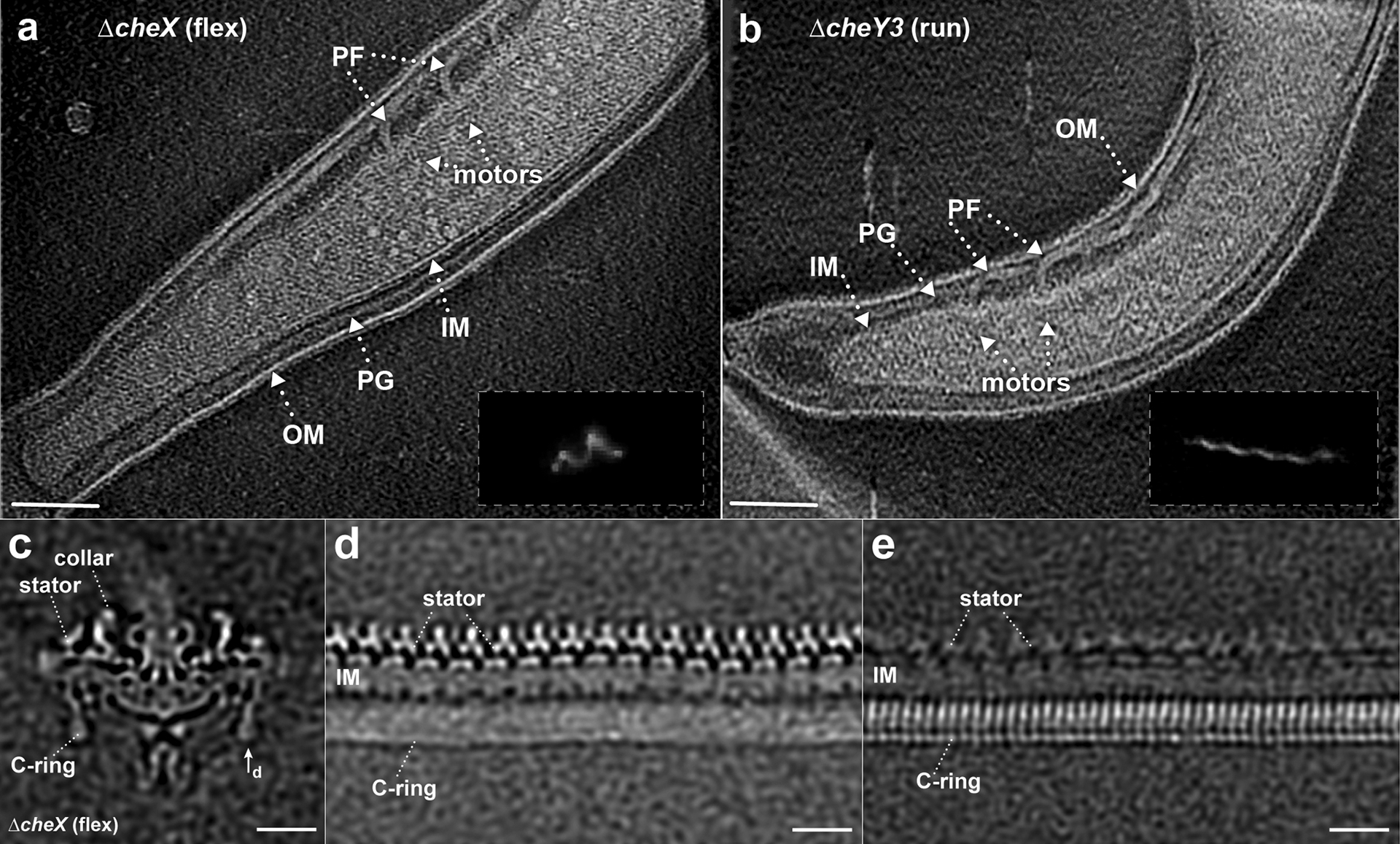
(a) A representative tomographic section from a ΔcheX cell tip reconstruction. Outer membrane (OM), inner membrane (IM), peptidoglycan layer (PG), and motors are clearly resolved in the tomogram. (b) A representative section of a tomogram from a ΔcheY3 cell tip. Multiple motors with different orientations can be found at the cell tip. The insertions in (a, b) are the dark-field images showing a ΔcheX cell constantly flexing and a constantly running ΔcheY3 cell, respectively. (c) A medial cross-section of an averaged map of the ΔcheX motor. (d) The unrolled map refined using the stator region densities shows 16 stator complexes are embedded in the inner membrane (IM), while the C-ring subunits are unresolved due to symmetry mismatch between the C-ring and the stator. (e) The unrolled map refined using the C-ring region densities shows 46-fold symmetric features, while the stator becomes blurry. Bar = 20 nm.
Extended Data Fig. 3. Comparison between in situ stator complex and the purified stator components.

(a) Structure of purified MotA complex from A. aeolicus resolved by single particle EM (EMD 3417)63. (b) The in situ stator complex in the ΔcheX motor has a bell-shaped structure embedded in the inner membrane (IM) and a periplasmic domain. The top part of the periplasmic domain matches well with the crystal structure of the S. enterica MotB periplasmic domain (PDB 2ZVY)62 (middle panel). The bell-shaped structure has similar size and shape as the structure of EMD 3417 (right panel). (c) The in situ stator complex in the ΔcheY3-Class-2 motor is similar to that in the ΔcheX motor.
Extended Data Fig. 4. Schematic diagram for the in-frame replacement of cheX-cheY3 genes with cheY3-gfp.

(a) aadA, a streptomycin resistance gene was used as a selection marker. pcheX(F) and GFP (R) are oligonucleotide primers utilized to verify the occurrence of the allelic exchange of the recombinant construct (bottom) into the targeted region in the B. burgdorferi chromosome (top). (b) Ni-NTA affinity purification using FLAG-tagged FliM (FliM-FLAG) and FLAG-tagged FliN (FliN-FLAG) to pull down HisCheY3 or HisCheY3* (CheY3D79A), respectively. HisCheY3 was co-purified with FliM-FLAG (b), but not with FliN-FLAG (c), suggesting that CheY3 does not bind on FliN. In contrast, more HisCheY3 protein was co-purified with FliM-FLAG with acetyl phosphate (b), and HisCheY3* was not co-purified with FliM-FLAG (a) or FliN-FLAG (c). These results indicate that CheY3 binds to FliM protein in a phosphorylation-dependent manner.
Extended Data Fig. 5. Motor structures in constantly running ΔcheY3 cells.
(a) A medial cross-section of an averaged structure in ΔcheY3 B. burgdorferi cell. (b, c) Cross-sections show the stator ring and the C-ring, respectively. (d) Focused structure of the C-ring (unrolled along the central rod). Two distinct classes in the ΔcheY3 cells are named as ΔcheY3-Class-1 (e-h) and ΔcheY3-Class-2 (i-l). Class-1 and Class-2 account ~45% and ~55% of all the ΔcheY3 motors we used for current work, respectively. The stator structures in Class-1 and Class-2 (f and j) are quite similar, while the C-ring subunits (compare h with l) are tilted in different directions.
Extended Data Fig. 6. Motors adopt distinct conformations at the two cell poles in the same ΔcheY3 cell.

(a) A tomographic section from one cell tip showed in panel b. (b) An overview of one intact ΔcheY3 cell. (c) A tomographic section from another tip of the same cell in panel b. The motors at each cell tip were aligned separately, then focused refined to the C-ring. (d-f) The motors from one cell tip have CCW conformation. (g-t) The motors from another tip appear to adopt CW conformation. (j-l) Averaged structure from motors located at one tip of five cells shows a better structure with CCW conformation. (m-o) Averaged structure from motors located at another tip of five cells shows a better structure with CW conformation. Bar = 200 nm in (a, c). Bar = 1 μm in (b).
Extended Data Fig. 7. CheY3-P binding triggers conformational change.

(a-d) Comparison between the C-ring models before (grey, top left in each panel) and after (colored, top right in each panel) CheY3-P binding. (e) The dash framed regions in panel a are overlapped to show their differences. The N-terminal domain of FliM (FliMN) folds out ~154° to interact with CheY3-P. (f) Binding of CheY3-P induces ~27° tilt of the FliM middle domain (FliMM). (g, h) FliG2 undergoes a large tilt and alters the interactions between FliG2 and MotA. The charged residues (Lys275, Arg292, Glu299, and Asp300) in the C-terminal domain of FliG2 (FliG2C) are colored in red.
Extended Data Fig. 8. Comparison of the C-ring structures in CCW and CW rotation.

(a, b) Diameters of the FliG2C, FliM and FliN rings in the C-ring with CCW rotation (ΔcheY3-class-2). (c-d) Diameters of the FliG2, FliM and FliN rings in the C-ring with CW rotation (ΔcheX).
Extended Data Fig. 9. Motility model for B. burgdorferi.

(a, b) In the default state, the concentration of CheY3-P is low, and the cell runs. The motors at the anterior cell pole rotate CCW, and the motors at the posterior cell pole rotate CW. Binding of unidentified proteins (grey circles at the inner side of the C-ring) to the C-ring at the posterior cell pole likely changes the motor to a CW conformation. (c, d) At high concentrations of CheY3-P, the CCW rotating motors switch to CW rotation, while the CW rotating motors keep turning CW. Thus, the motors at both cell poles rotate CW and the cell flexes. After the flex, the direction of flagellar rotation at the two poles can switch so that the cell reverses the direction of its run.
Extended Data Fig. 10. Oligonucleotide primers used in this study.
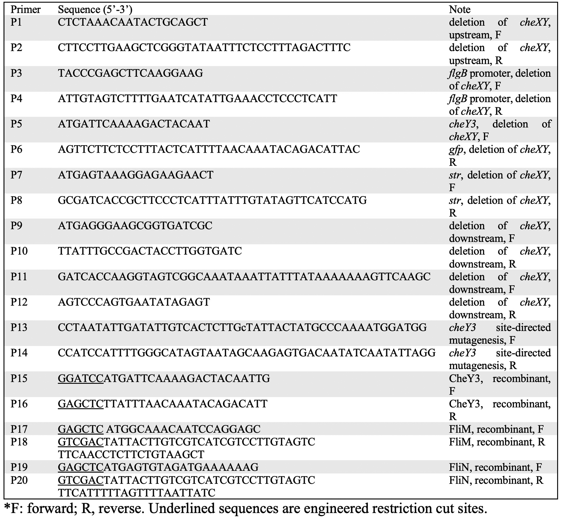
*F: forward; R, reverse. Underlined sequences are engineered restriction cut sites.
Supplementary Material
Supplementary Video 1. ΔcheX cells flex in the video.
Supplementary Video 2. A refined structure of the motor in the ΔcheX mutant.
Supplementary Video 3. ΔcheY3 cells constantly run in the video.
Supplementary Video 4. A class average of the motor in the ΔcheY3 mutant.
Supplementary Video 5. Another class average of the motor in the ΔcheY3 mutant.
Supplementary Video 6. Animation showing flagellar rotational switching in the Lyme disease spirochete.
Acknowledgements
We thank Michael Manson, Justin Radolf, Seiji Kojima, and Michio Homma for critical reading and suggestion. This work was supported by grants from the National Institute of Allergy and Infectious Diseases (R01AI087946, R01AI078958, R01AI132818, and R01AI59048) and the National Institute of Dental and Craniofacial Research (R01DE023080). This work is dedicated to the memory of Prof. Fanghua Li, who was an incredible scientist and a trusted mentor for YC, JL, and many others in the field of electron microscopy.
Footnotes
Data availability
Cryo-EM density maps that support the local refined ΔcheX (EMD 21885) and ΔcheY3 (Class-1: EMD 21884, Class-2: EMD 21886) motor structures determined by cryo-electron tomography have been deposited in the Electron Microscopy Data Bank (EMDB). Other maps and models are available upon request.
Competing interest statement
The authors declare no competing interests.
References
- 1.Berg HC The rotary motor of bacterial flagella. Annu Rev Biochem 72, 19–54 (2003). [DOI] [PubMed] [Google Scholar]
- 2.Chevance FF & Hughes KT Coordinating assembly of a bacterial macromolecular machine. Nat Rev Microbiol 6, 455–65 (2008). [DOI] [PMC free article] [PubMed] [Google Scholar]
- 3.Minamino T, Kinoshita M & Namba K Directional Switching Mechanism of the Bacterial Flagellar Motor. Comput Struct Biotechnol J 17, 1075–1081 (2019). [DOI] [PMC free article] [PubMed] [Google Scholar]
- 4.Terashima H, Kojima S & Homma M Flagellar motility in bacteria structure and function of flagellar motor. Int Rev Cell Mol Biol 270, 39–85 (2008). [DOI] [PubMed] [Google Scholar]
- 5.Wadhams GH & Armitage JP Making sense of it all: bacterial chemotaxis. Nat Rev Mol Cell Biol 5, 1024–37 (2004). [DOI] [PubMed] [Google Scholar]
- 6.Parkinson JS, Hazelbauer GL & Falke JJ Signaling and sensory adaptation in Escherichia coli chemoreceptors: 2015 update. Trends Microbiol 23, 257–66 (2015). [DOI] [PMC free article] [PubMed] [Google Scholar]
- 7.Rossmann FM, Hug I, Sangermani M, Jenal U & Beeby M In situ structure of the Caulobacter crescentus flagellar motor and visualization of binding of a CheY-homolog. Mol Microbiol, in press. [DOI] [PMC free article] [PubMed] [Google Scholar]
- 8.Lele PP, Branch RW, Nathan VS & Berg HC Mechanism for adaptive remodeling of the bacterial flagellar switch. Proc Natl Acad Sci U S A 109, 20018–22 (2012). [DOI] [PMC free article] [PubMed] [Google Scholar]
- 9.Delalez NJ, Berry RM & Armitage JP Stoichiometry and Turnover of the Bacterial Flagellar Switch Protein FliN. mBio 5, e01216–14 (2014). [DOI] [PMC free article] [PubMed] [Google Scholar]
- 10.Charon NW et al. The unique paradigm of spirochete motility and chemotaxis. Annu Rev Microbiol 66, 349–370 (2012). [DOI] [PMC free article] [PubMed] [Google Scholar]
- 11.Nakamura S Spirochete Flagella and Motility. Biomolecules 10(2020). [DOI] [PMC free article] [PubMed] [Google Scholar]
- 12.Berg HC How spirochetes may swim. J Theor Biol 56, 269–73 (1976). [DOI] [PubMed] [Google Scholar]
- 13.Li C et al. Asymmetrical flagellar rotation in Borrelia burgdorferi nonchemotactic mutants. Proc Natl Acad Sci U S A 99, 6169–74 (2002). [DOI] [PMC free article] [PubMed] [Google Scholar]
- 14.Motaleb MA, Liu J & Wooten RM Spirochetal motility and chemotaxis in the natural enzootic cycle and development of Lyme disease. Curr Opin Microbiol 28, 106–13 (2015). [DOI] [PMC free article] [PubMed] [Google Scholar]
- 15.Motaleb MA et al. CheX is a phosphorylated CheY phosphatase essential for Borrelia burgdorferi chemotaxis. J Bacteriol 187, 7963–9 (2005). [DOI] [PMC free article] [PubMed] [Google Scholar]
- 16.Chen S et al. Structural diversity of bacterial flagellar motors. EMBO J 30, 2972–81 (2011). [DOI] [PMC free article] [PubMed] [Google Scholar]
- 17.Zhao X, Norris SJ & Liu J Molecular architecture of the bacterial flagellar motor in cells. Biochemistry 53, 4323–33 (2014). [DOI] [PMC free article] [PubMed] [Google Scholar]
- 18.Kojima S & Blair DF The bacterial flagellar motor: structure and function of a complex molecular machine. Int Rev Cytol 233, 93–134 (2004). [DOI] [PubMed] [Google Scholar]
- 19.Chang Y et al. Structural insights into flagellar stator-rotor interactions. Elife 8(2019). [DOI] [PMC free article] [PubMed] [Google Scholar]
- 20.Zhou J, Lloyd SA & Blair DF Electrostatic interactions between rotor and stator in the bacterial flagellar motor. Proc Natl Acad Sci U S A 95, 6436–41 (1998). [DOI] [PMC free article] [PubMed] [Google Scholar]
- 21.Chun SY & Parkinson JS Bacterial motility: membrane topology of the Escherichia coli MotB protein. Science 239, 276–8 (1988). [DOI] [PubMed] [Google Scholar]
- 22.Kojima S et al. The Helix Rearrangement in the Periplasmic Domain of the Flagellar Stator B Subunit Activates Peptidoglycan Binding and Ion Influx. Structure 26, 590–598.e5 (2018). [DOI] [PubMed] [Google Scholar]
- 23.Lloyd SA & Blair DF Charged residues of the rotor protein FliG essential for torque generation in the flagellar motor of Escherichia coli. J Mol Biol 266, 733–44 (1997). [DOI] [PubMed] [Google Scholar]
- 24.Li C, Xu H, Zhang K & Liang FT Inactivation of a putative flagellar motor switch protein FliG1 prevents Borrelia burgdorferi from swimming in highly viscous media and blocks its infectivity. Mol Microbiol 75, 1563–1576 (2010). [DOI] [PMC free article] [PubMed] [Google Scholar]
- 25.Deme JC et al. Structures of the stator complex that drives rotation of the bacterial flagellum. bioRxiv, 2020.05.12.089201 (2020). [DOI] [PMC free article] [PubMed] [Google Scholar]
- 26.Santiveri M et al. Structure and function of stator units of the bacterial flagellar motor. bioRxiv, 2020.05.15.096610 (2020). [DOI] [PubMed] [Google Scholar]
- 27.Takekawa N et al. The tetrameric MotA complex as the core of the flagellar motor stator from hyperthermophilic bacterium. Sci Rep 6, 31526 (2016). [DOI] [PMC free article] [PubMed] [Google Scholar]
- 28.Kojima S et al. Stator assembly and activation mechanism of the flagellar motor by the periplasmic region of MotB. Mol Microbiol 73, 710–8 (2009). [DOI] [PubMed] [Google Scholar]
- 29.Thomas DR, Francis NR, Xu C & DeRosier DJ The Three-Dimensional Structure of the Flagellar Rotor from a Clockwise-Locked Mutant of Salmonella enterica Serovar Typhimurium. J Bacteriol 188, 7039–7048 (2006). [DOI] [PMC free article] [PubMed] [Google Scholar]
- 30.Motaleb MA, Sultan SZ, Miller MR, Li C & Charon NW CheY3 of Borrelia burgdorferi is the key response regulator essential for chemotaxis and forms a long-lived phosphorylated intermediate. J Bacteriol 193, 3332–41 (2011). [DOI] [PMC free article] [PubMed] [Google Scholar]
- 31.McDowell MA et al. Characterisation of Shigella Spa33 and Thermotoga FliM/N reveals a new model for C-ring assembly in T3SS. Mol Microbiol 99, 749–766 (2016). [DOI] [PMC free article] [PubMed] [Google Scholar]
- 32.Carroll BL et al. The flagellar motor of Vibrio alginolyticus undergoes major structural remodeling during rotational switching. bioRxiv (2020). [DOI] [PMC free article] [PubMed] [Google Scholar]
- 33.Leake MC et al. Stoichiometry and turnover in single, functioning membrane protein complexes. Nature 443, 355–8 (2006). [DOI] [PubMed] [Google Scholar]
- 34.Vartanian AS, Paz A, Fortgang EA, Abramson J & Dahlquist FW Structure of flagellar motor proteins in complex allows for insights into motor structure and switching. J Biol Chem 287, 35779–83 (2012). [DOI] [PMC free article] [PubMed] [Google Scholar]
- 35.Lee LK, Ginsburg MA, Crovace C, Donohoe M & Stock D Structure of the torque ring of the flagellar motor and the molecular basis for rotational switching. Nature 466, 996–1000 (2010). [DOI] [PMC free article] [PubMed] [Google Scholar]
- 36.Minamino T et al. Structural insight into the rotational switching mechanism of the bacterial flagellar motor. PLoS Biol 9, e1000616 (2011). [DOI] [PMC free article] [PubMed] [Google Scholar]
- 37.Li C et al. Asymmetrical flagellar rotation in Borrelia burgdorferi nonchemotactic mutants. Proc Natl Acad Sci U S A 99, 6169–74 (2002). [DOI] [PMC free article] [PubMed] [Google Scholar]
- 38.Sze CW et al. Study of the Response Regulator Rrp1 Reveals Its Regulatory Role in Chitobiose Utilization and Virulence of Borrelia burgdorferi. Infect Immun 81, 1775–1787 (2013). [DOI] [PMC free article] [PubMed] [Google Scholar]
- 39.Motaleb MA et al. CheX is a phosphorylated CheY phosphatase essential for Borrelia burgdorferi chemotaxis. J Bacteriol 187, 7963–9 (2005). [DOI] [PMC free article] [PubMed] [Google Scholar]
- 40.Motaleb MA, Pitzer JE, Sultan SZ & Liu J A novel gene inactivation system reveals altered periplasmic flagellar orientation in a Borrelia burgdorferi fliL mutant. J Bacteriol 193, 3324–31 (2011). [DOI] [PMC free article] [PubMed] [Google Scholar]
- 41.Mastronarde DN Automated electron microscope tomography using robust prediction of specimen movements. J Struct Biol 152, 36–51 (2005). [DOI] [PubMed] [Google Scholar]
- 42.Eisenstein F, Danev R & Pilhofer M Improved applicability and robustness of fast cryo-electron tomography data acquisition. J Struct Biol 208, 107–114 (2019). [DOI] [PMC free article] [PubMed] [Google Scholar]
- 43.Zheng SQ et al. MotionCor2: anisotropic correction of beam-induced motion for improved cryo-electron microscopy. Nature Methods 14, 331 (2017). [DOI] [PMC free article] [PubMed] [Google Scholar]
- 44.Kremer JR, Mastronarde DN & McIntosh JR Computer Visualization of Three-Dimensional Image Data Using IMOD. Journal of Structural Biology 116, 71–76 (1996). [DOI] [PubMed] [Google Scholar]
- 45.Zhang K Gctf: Real-time CTF determination and correction. J Struct Biol 193, 1–12 (2016). [DOI] [PMC free article] [PubMed] [Google Scholar]
- 46.Zhu S, Qin Z, Wang J, Morado DR & Liu J In Situ Structural Analysis of the Spirochetal Flagellar Motor by Cryo-Electron Tomography. Methods Mol Biol 1593, 229–242 (2017). [DOI] [PubMed] [Google Scholar]
- 47.Winkler H 3D reconstruction and processing of volumetric data in cryo-electron tomography. Journal of Structural Biology 157, 126–137 (2007). [DOI] [PubMed] [Google Scholar]
- 48.Winkler H et al. Tomographic subvolume alignment and subvolume classification applied to myosin V and SIV envelope spikes. J Struct Biol 165, 64–77 (2009). [DOI] [PMC free article] [PubMed] [Google Scholar]
- 49.Liu J, Wright ER & Winkler H Chapter Thirteen - 3D Visualization of HIV Virions by Cryoelectron Tomography. in Methods in Enzymology, Vol. 483 (ed. Jensen GJ) 267–290 (Academic Press, 2010). [DOI] [PMC free article] [PubMed] [Google Scholar]
- 50.Vartanian AS, Paz A, Fortgang EA, Abramson J & Dahlquist FW Structure of flagellar motor proteins in complex allows for insights into motor structure and switching. J Biol Chem 287, 35779–83 (2012). [DOI] [PMC free article] [PubMed] [Google Scholar]
- 51.Lee LK, Ginsburg MA, Crovace C, Donohoe M & Stock D Structure of the torque ring of the flagellar motor and the molecular basis for rotational switching. Nature 466, 996–1000 (2010). [DOI] [PMC free article] [PubMed] [Google Scholar]
- 52.Notti RQ, Bhattacharya S, Lilic M & Stebbins CE A common assembly module in injectisome and flagellar type III secretion sorting platforms. Nat Commun 6, 7125 (2015). [DOI] [PMC free article] [PubMed] [Google Scholar]
- 53.Brown PN, Mathews MAA, Joss LA, Hill CP & Blair DF Crystal Structure of the Flagellar Rotor Protein FliN from Thermotoga maritima. J Bacteriol 187, 2890 (2005). [DOI] [PMC free article] [PubMed] [Google Scholar]
- 54.Ahn D-R, Song H, Kim J, Lee S & Park S The crystal structure of an activated Thermotoga maritima CheY with N-terminal region of FliM. Int J Biol Macromol 54, 76–83 (2013). [DOI] [PubMed] [Google Scholar]
- 55.Roy A, Kucukural A & Zhang Y I-TASSER: a unified platform for automated protein structure and function prediction. Nat Protoc 5, 725–38 (2010). [DOI] [PMC free article] [PubMed] [Google Scholar]
- 56.Yang J et al. The I-TASSER Suite: protein structure and function prediction. Nat Methods 12, 7–8 (2015). [DOI] [PMC free article] [PubMed] [Google Scholar]
- 57.Yang J & Zhang Y I-TASSER server: new development for protein structure and function predictions. Nucleic Acids Res 43, W174–81 (2015). [DOI] [PMC free article] [PubMed] [Google Scholar]
- 58.Pettersen EF et al. UCSF Chimera—A visualization system for exploratory research and analysis. J Comp Chem 25, 1605–1612 (2004). [DOI] [PubMed] [Google Scholar]
- 59.Lyskov S & Gray JJ The RosettaDock server for local protein-protein docking. Nucleic Acids Res 36, W233–8 (2008). [DOI] [PMC free article] [PubMed] [Google Scholar]
- 60.Afonine PV, Grosse-Kunstleve RW, Adams PD & Urzhumtsev A Bulk-solvent and overall scaling revisited: faster calculations, improved results. Acta Crystallogr D Biol Crystallogr 69, 625–34 (2013). [DOI] [PMC free article] [PubMed] [Google Scholar]
- 61.Kojima S et al. Stator assembly and activation mechanism of the flagellar motor by the periplasmic region of MotB. Mol microbiol 73, 710–718 (2009). [DOI] [PubMed] [Google Scholar]
- 62.Takekawa N et al. The tetrameric MotA complex as the core of the flagellar motor stator from hyperthermophilic bacterium. Sci Rep 6, 31526 (2016). [DOI] [PMC free article] [PubMed] [Google Scholar]
- 63.Goddard TD et al. UCSF ChimeraX: Meeting modern challenges in visualization and analysis. Prot Sci 27, 14–25 (2018). [DOI] [PMC free article] [PubMed] [Google Scholar]
Associated Data
This section collects any data citations, data availability statements, or supplementary materials included in this article.
Supplementary Materials
Supplementary Video 1. ΔcheX cells flex in the video.
Supplementary Video 2. A refined structure of the motor in the ΔcheX mutant.
Supplementary Video 3. ΔcheY3 cells constantly run in the video.
Supplementary Video 4. A class average of the motor in the ΔcheY3 mutant.
Supplementary Video 5. Another class average of the motor in the ΔcheY3 mutant.
Supplementary Video 6. Animation showing flagellar rotational switching in the Lyme disease spirochete.