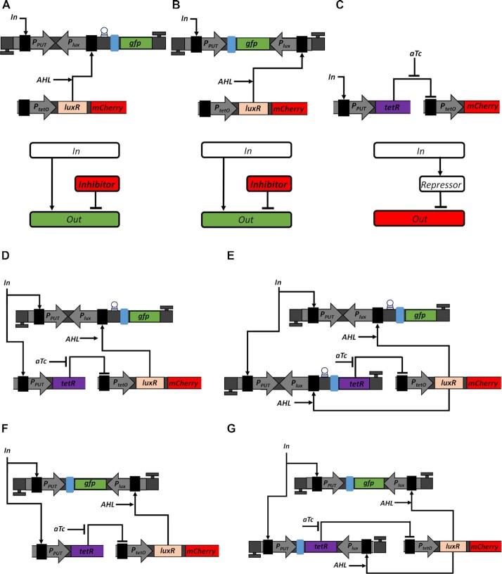
Figure 5.
Implementation of ICF and DNF designs in living cells. (A) Utilization of transcriptional interference to mimic subtraction. The PPUT activates GFP signal. The Plux reverse promoter is located opposite to PPUT and upstream to gfp gene repressing GFP signal. The first unidirectional terminator is in the same orientation as PPUT and downstream to gfp gene. The second unidirectional terminator is in the same orientation as Plux and upstream to PPUT. The terminator is represented by a highlighted letter T. The RBS is marked by a blue rectangle. The riboj sequence is inserted upstream of the RBS which is marked by a circle (59). The LuxR transcription activator and mCherry are expressed under PtetO promoter, encoded on MCP. When no TetR is expressed, PtetO acts as a constitutive promoter. Both LuxR and mCherry genes have their own RBS sequences. The unit Terminator_RC-PPUT-Plux_RC-GFP-Terminator is encoded on HCP. The block diagram describes the operation of OL circuit, where the output is regulated both by the input and inhibitor. (B) Utilizing antisense transcription to mimic subtraction. The Plux promoter is oriented in reverse to PPUT and downstream to gfp gene repressing GFP signal. The first unidirectional terminator was placed in the same orientation to PPUT and downstream to gfp gene. The second unidirectional terminator was placed in the same orientation to Plux and upstream to PPUT. The LuxR activator and mCherry are expressed by PtetO promoter encoded on MCP. Both LuxR and mCherry genes have their own RBS sequences. The unit Terminator_RC-PPUT-GFP-Plux_RC-Terminator is encoded on HCP. The block diagram describes the operation of OL, where both input and inhibitor regulate the output level. (C) Implementation of an inverting switch using TetR repressor. The PPUT controls the expression of TetR, which represses the activity of PtetO. The small molecule aTc binds TetR to release the repression of PtetO. The PtetO-mCherry-Terminator construct was placed on MCP, while the PPUT-TetR-Terminator construct was cloned on LCP in order to match their copy numbers in ICF and DNF circuits. The mCherry gene was further replaced by LuxR gene to be integrated in ICF and DNF circuits. The block diagram describes the operation of an inverting switch circuit. (D) Implementation of ICF circuit by combining a transcriptional interference unit with TetR inverting switch. Here TetR is controlled only by PPUT. (E) Implementation of a DNF circuit by combining transcriptional interference unit with TetR inverting switch. Here TetR is controlled by both PPUT and Plux promoters. (F) Implementation of ICF circuit by combining an antisense transcription unit with TetR inverting switch. Here TetR is controlled only by PPUT. (G) Implementation of a DNF circuit by combining an antisense transcription with TetR inverting switch. Here TetR is controlled by both promoters PPUT and Plux.

