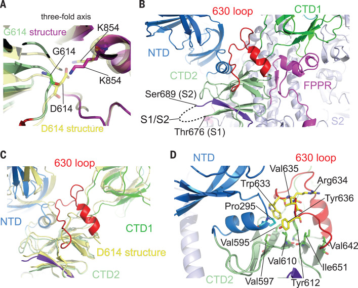
Fig. 4. Close-up views of the D614G substitution.
(A) A close-up view of the region near the residue 614 with superposition of the G614 trimer structure in green (CTD2) and magenta (FPPR) and the D614 trimer in yellow, both in the closed prefusion conformation. Residues G614, D614, and two K854s from both structures are shown in stick model. The direction of the three-fold axis of the trimer is indicated. (B) Location of the 630 loop in the S trimer. The 630 loop is highlighted in red, the NTD in blue, the CTD1 in green, the CTD2 in light green, the S2 in light blue, and the FPPR from a neighboring protomer in magenta. The S1-S2 boundary and the nearest ordered residues Thr676 from S1 and Ser689 from S2 are all indicated. A strand from the N-terminal end of S2, packed in the CTD2, is highlighted in purple. (C) A view showing that the 630 loop wedges between the NTD and the CTD1 and pushes them apart. (D) Packing of the 630 loop against the hydrophobic surface formed by residues Val595, Val597, Val610, Tyr612, Val642, and Ile651 from the CTD2 and Pro295 from the NTD. Residues Trp633 and Val635 from the 630 loop contribute to this interaction.

