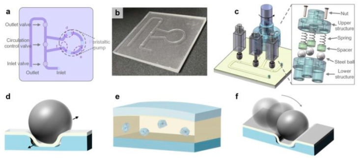
Figure 13.
The pump-on-chip cell disruption microfluidic chip utilized in [50]; (a) schematic of the device, (b) picture of the fabricated cell disruption microfluidic chip. (c) Schematic of the platform with the on-chip micropump, electromagnets. (d) Cells in the sample leaking through the gap between the channel corners and the PDMS membrane are pulverized by the steel balls. (e) The compressive stress makes cells deform. (f) Some cells are crushed down by the steel balls. Adapted with permission from [50]. Copyright 2017 AIP Publishing.

