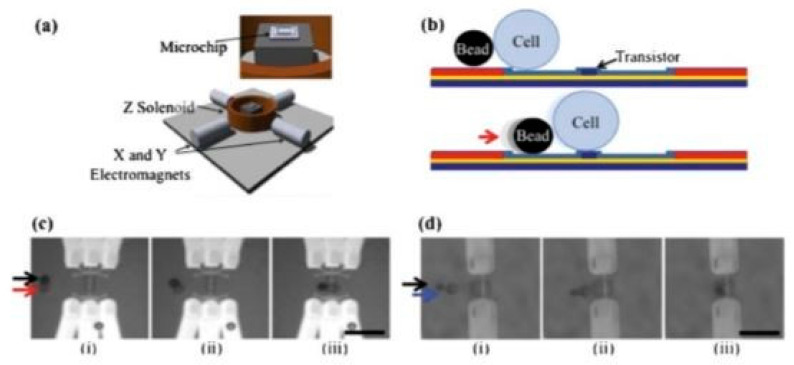
Figure 19.
(a) Schematic of the magnetic bead setup utilized in [72]. The electromagnets generate a magnetic field, which rolls magnetic beads across the chip surface. (b) The beads are used to push the cells into position above the transistor. (c) An MCF-7 cell (red arrow) is moved from left to right by a bead (black arrow) to a position over a set of nanowires. (d) An HT-29 cell (blue arrow) is moved from left to right by a bead (black arrow) and positioned over a nanoribbon. Adapted with permission from [72]. Copyright 2013 Royal Society of Chemistry.

