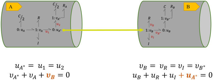
Fig 5. Conservation equations at the terminal junctions in two coupled bond graph modules.
vB in B is added to the conservation equation at 0 : uA* junction in A and uA* in A is added to the conservation equation at 1 : vB junction in B. Each terminal junction’s v or u in each module is added to the other module’s conservation equation, representing the addition of a bond.

