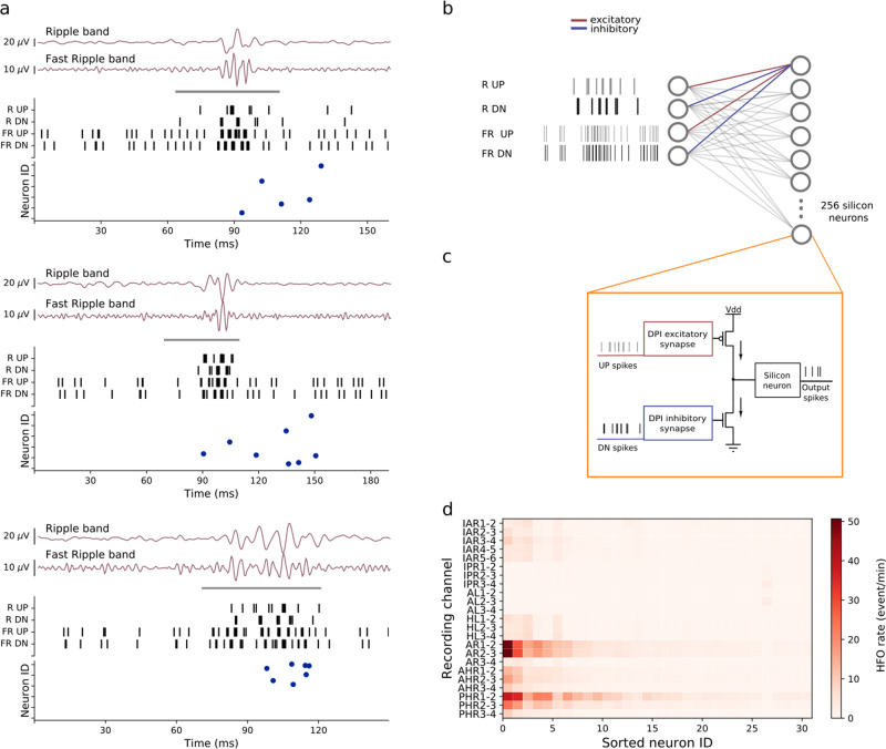
Fig. 5. Network spiking characteristics.
a Examples of HFO that the hardware SNN detected in the iEEG of Patient 1. The periods marked by the gray bar represent clinically relevant HFO31,43. The signals in Ripple and Fast-ripple band were transformed to UP and DN spikes. These spike trains were sent to the neurons in the hardware through the RUP, RDN, FRUP and FRDN channels. The bottom panel of each example shows the raster plot of the silicon neurons. Each neuron responds to different HFO depending on the characteristics of the pattern. b The SNN architecture consist of a two-layer network of 256 integrate and fire neurons with dynamic synapses. Each neuron in the second layer receives excitatory connections from the RUP and FRUP channels, and inhibitory connections from the RDN and FRDN channels. The synaptic parameters time constants and weights are distributed randomly within a predetermined optimal range. c Hardware building blocks used for the implementations of the SNN: the DPI synapse is a "Differential-Pair Integrator'' circuit59, and the silicon neuron is an Adaptive Exponential Integrate and Fire (AdExp IF) circuit81. d HFO rates computed for Patient 1. The neurons are sorted according to their average firing rate. Only a small number of neurons fire across all the recordings, even for channels with high HFO rates (e.g., AR1-2).

