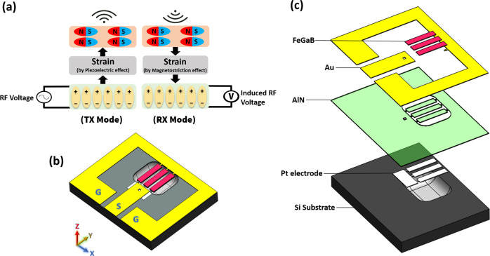
Fig. 1. 3D structure and operating concept of the proposed ME antenna.
a Diagram showing the concept of Tx and Rx operating modes of ME antenna, where the top and bottom rectangular boxes represent the magnetostrctive and piezoelectric layers, respectively; b 3D schematic of the ME antenna on released Si substrate. The yellow color indicates a gold ground ring and GSG pads that are used for probing and wire-bonding the antenna to PCB; c exploded structure of the ME antenna showing all the layers.

