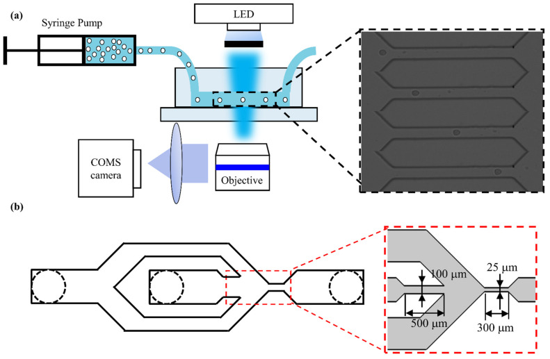
Figure 1.
(a) The overview of the experimental system device and its detailed work schematic diagram and microfluidic channel geometry. The inset shows that cells flow through the constriction channel. (b) The improved microfluidic chip structure. The insets show the microchannel structure of the microfluidic chip.

