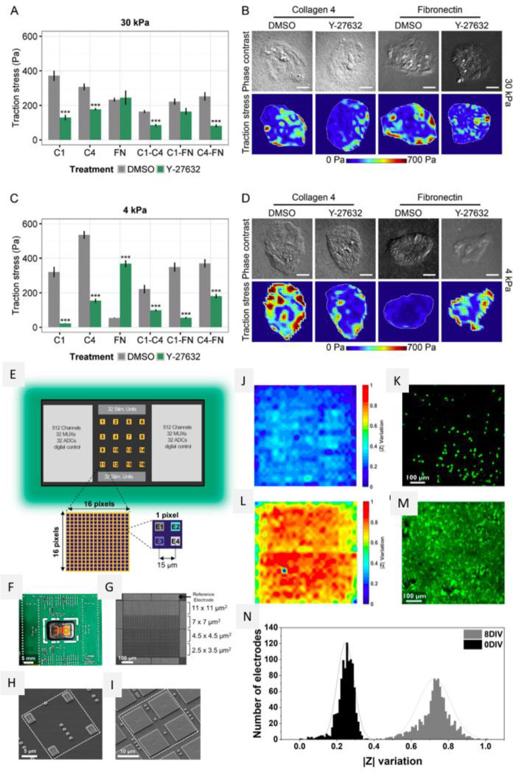
Figure 26.
Microarray strategies to investigate cell responses to mechanical stimuli. (A–D) Evaluation of cell traction stress. (A, C) Cell traction stress (Pa) measured on the microarrays on 30 kPa (A) and 4 kPa (C) substrates on the different protein compositions, in control (DMSO) and ROCK inhibiting (Y-27623, 10 μM) media conditions. (B, D) Representative phase contrast micrographs and heat maps of traction stress for 30 kPa (B) and 4 kPa (D) substrates. Student’s t tests were performed against DMSO within each ECM combination, and data is presented as mean ± SEM with n = 3 and ≈ 20 total islands per condition (P < 0.05 (∗), P < 0.01 (∗∗), P < 0.001 (∗∗∗)). The scale bar is 50 μm. Reprinted with permission from ref (541). Copyright 2016 Elsevier, Ltd. (E–N) Microarray strategy. (E) Schematic of the overall microarray chip with zoom on a single active area and on a single pixel, (F) picture of the chip bonded on the carrier, (G) SEM image of one active area featuring the 4 different electrode sizes and the 8 reference electrodes. (H, I) SEM images of a single pixel, containing electrodes of sizes 2.5 × 3.5 μm2 (H) or 11 × 11 μm2 (I). (J–N) Electrical and confocal imaging of primary hippocampal neuron culture at 0 and 8 days in vitro. (J, K) Electrical impedance map and confocal image of the cells stained with Calcein AM 4.5 h after seeding. (L, M) Electrical impedance map and confocal images corresponding to the same chip surface area (2500 μm2). (N) Histogram illustrating the distribution of the relative impedance variation recorded by the electrodes for cells after 0 (black) and 8 (gray) days in vitro. Reprinted with permission from ref (551). Copyright 2019 Frontiers.

