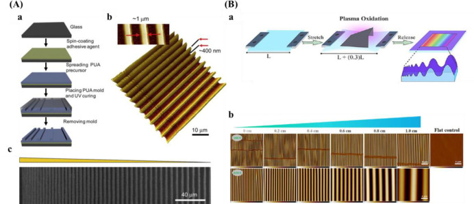
Figure 7.
Schematic diagrams for preparing anisotropic gradient. (A) Arrays with varied intervals prepared by UV-assisted capillary force lithography. (a) Schematic of the preparation process for pattern arrays. (b) 3D AFM picture. (c) SEM image. Reprinted with permission from ref (160). Copyright 2009 Elsevier, Ltd. (B) (a) Procedure for the fabrication of wrinkle gradient. (b) AFM pictures along the gradient. Reprinted with permission from ref (100). Copyright 2017 American Chemical Society.

