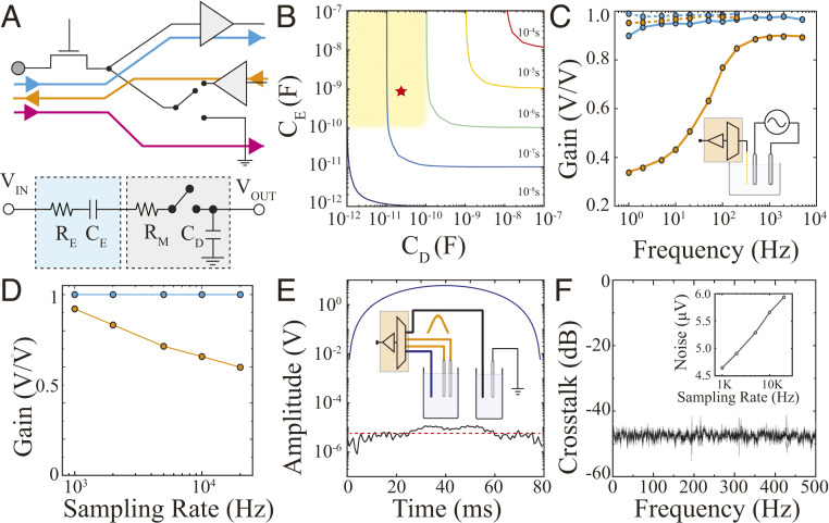
Fig. 1.
MTA enables a high sampling rate, uniform gain and low-noise acquisition, as well as stimulation via neural interface devices. (A) Schematic highlighting the acquisition (blue), stimulation (orange), and grounding (pink) signal pathways of MTA (Top). A simplified circuit diagram of MTA consists of an RC model representing an electrode (cyan), and a switch with the line resistance (RM) and drain capacitance (CD) forming a multiplexer (gray; Bottom). (B) Temporal response of MTA under different electrode/multiplexer configurations. The colored lines indicate sampling rate defined as 10 times the rise time (10 × τRC). The yellow-shaded box shows parameters compatible with MTA design and acquisition of action potentials from neural interface devices. The red star denotes the CD and CE of experimental data in this work. (C) Frequency responses of MTA-based acquisition devices combined with high-impedance tungsten-based electrodes (100 KΩ at 1 KHz, orange) and low-impedance PEDOT:PSS-based electrodes (3 KΩ at 1 KHz, blue). The dashed and solid lines represent 1,250 Hz and 20 KHz sampling rates, respectively. Inset: A schematic of the experimental setup with a pair of bipolar stimulating electrodes (gray) that generate a 1 mV sweep signal (1 to 104 Hz) in PBS which is acquired by a microelectrode combined with MTA device (orange). (D) Gain versus sampling rate relationship at 100 Hz for 50 µm diameter tungsten- (orange) and PEDOT:PSS-based (blue) electrodes. (E) Evaluation for cross-talk during simultaneous recording and stimulation was performed using two PBS-filled chambers connected to adjacent multiplexed channels within the MTA device and a stimulating electrode delivering Gaussian stimulation (Inset). The recording electrode (blue) placed in the same chamber as the stimulating electrode (orange) captured the Gaussian input (blue trace), while the recording electrode associated with the adjacent MTA channel (black) placed in the second chamber remained close to the noise floor (black trace compared to red dashed line). (F) Absence of cross-talk across the physiologically relevant frequency spectrum. Inset: Root mean squarenoise of the MTA device with different sampling rates.

