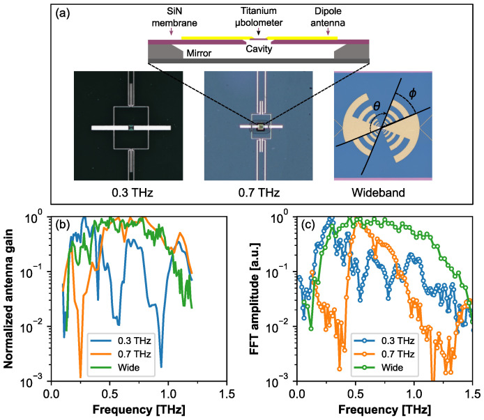
Figure 1.
The design and response spectra of antenna-coupled Ti-bolometers. Top panel (a): The design and schematic cross-section of the Ti-bolometer coupled with different antennas for 0.3 THz, 0.7 THz and for wideband detection (from left to right). Digital photos show top views of Ti-bolometer detectors coupled with dipole antenna design. The geometry of the titanium bridge amounts to 12 m length and 2 m width. The angles and in photo of the wideband detector are defined as sample rotation angle for polarization measurements and the polar angle of antenna fingers, respectively. The design is adapted from Refs. [22,23]. Panel (b): Simulated spectra of the normalized antenna gain for the different antenna’s designs. Panel (c): Response spectra of the devices were measured using Fourier transform far-infrared spectrometer as described in Ref. [22].

