
Fig. 3. Mechanism of the strain-insensitive conductance of LM sheath-core microfibers.
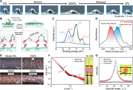
(A) Photographs of EGaIn droplet surface reconciliation on PVDF-HFP-TFE film during stretching and releasing. (B) Schematic illustration of the surface creation and readjustment of EGaIn on the PVDF-HFP-TFE film through the dipole-dipole interactions between Ga2O3 layer and polar C-F groups. (C) Ga 3d XPS spectrum of LM particles. a.u., arbitrary units. (D) Attenuated total reflection–Fourier transform infrared (ATR-FTIR) spectra of PVDF-HFP-TFE and PVDF-HFP-TFE/LM composite (CPVDF-HFP-TFE = 7 wt %) in the C-F stretching region. (E) Polarizing micrographs of the LM sheath-core microfiber during stretching observed in the reflection mode. (F) 2D SAXS patterns and scattering intensity plots against q (the integration area is the selected rectangular area) of the microfiber at strains of 0 and 300%, respectively. (G) SAXS azimuth integration and corresponding Lorentz fitting curve. The inset picture is the 2D image of the fiber at 300% strain. Photo credit: Lijing Zheng, Donghua University.