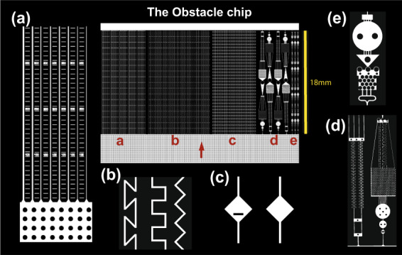
Fig. 2. Schematic overview of the design of the Obstacle Chip.

The chip design is shown in the centre, surrounded by enlarged details from the different experiments (a–e). The red arrow shows the hyphal growth direction. a Parallel straight channels in a series of different widths (20, 15, 10, 8, 6, 4 µm; n = 6) with each width repeated five times within the chip. Rulers were incorporated between the channels to measure how far the hyphae reached under microscope. b Channels of 10 µm width angled in a zigzag pattern with 90° corners, meandering square pattern with 90° corners or a z-shaped pattern with 135° corners, organised in a randomised order, n = 11. c Channels of 10 µm width with the repeated occurrence of 140-µm-diameter diamond-shaped openings that either was free for passage, included a 50-µm-wide and 10-µm-thick obstacle blocking the straight passage of the fungi, or a random occurrence of open and blocked openings in the same channel in randomised order, n = 12. d Larger obstacle courses with a combination of challenging structures for the fungi to navigate through. e Smaller-sized obstacle courses with more frequent repetition of obstacles.
