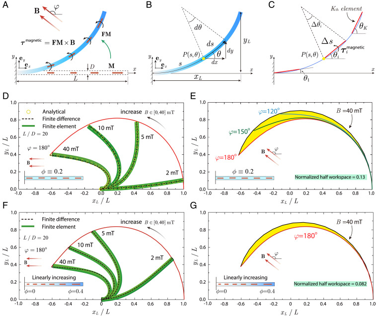
Fig. 3.
Theoretical modeling of the distal portion of an MSCR. (A) Schematic illustration of the distal portion of a MSCR with remanent magnetization along its axial direction deflecting toward the direction of the uniform actuation magnetic field B. The length and diameter of the distal portion are denoted as and , respectively. (B) The deformed distal portion is characterized by a parameterized spatial curve , referred to as an elastica, where and represent the arc length and tangential angle at the spatial point , respectively. The Cartesian coordinates of the distal tip are . (C) The finite difference method discretizes the elastica into elements in which the infinitesimal arc is approximated by a straight line . (D) Comparison of the deformation of the distal portion with uniform magnetic particle distribution under 180° magnetic field from the analytical solution, finite difference method, and finite element simulation. (E) The normalized half workspace of the MSCR with uniform magnetic particle distribution is 0.13. (F) Comparison of the deformation of the distal portion with linearly increasing particle concentration from 0 to 0.4 under 180° magnetic field from the finite difference method and finite element simulation. (G) The normalized half workspace of the MSCR with linearly increasing magnetic particle concentration from 0 to 0.4 is 0.082.

