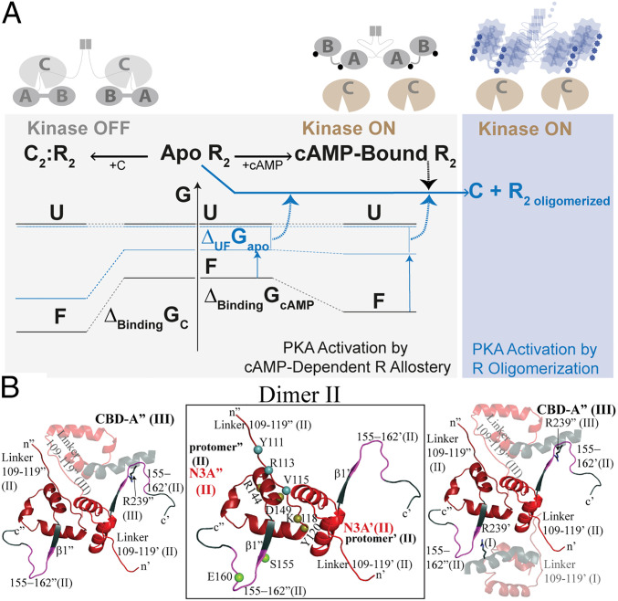
Fig. 6.
Proposed mechanism for the CNC PKA R1α mutations A211D and G287W. (A) Simplified free energy landscape diagram for PKA C activation and inhibition by wt (black) and CNC A211D and G287W (blue) PKA R1α, denoted here simply as R. Abbreviations: A, CBD-A of R; B, CBD-B of R; F, folded native structure of R; U, ensemble of unfolded and partially unfolded states of R (a single free energy level is shown to simplify the scheme); R2 oligomer, oligomerized form of the R dimer; G, Gibbs free energy; ΔUFGapo, unfolding free energy of apo R; ΔBindingGcAMP or C, free energy of cAMP or C binding to R. cAMP is shown as a circle. In the case of the CNC mutants, the circle is deformed to indicate that cAMP occupancies may change compared to wt. The specific mutant vs. wt free energy differences for apo U and apo F are unknown. In the CNC mutants, the ΔUFGapo and/or ΔBindingGcAMP free energies decrease relative to wt, resulting in higher populations of unfolded and/or partially unfolded conformers with exposed hydrophobic surfaces and aggregation-prone sites. Dashed arrows indicate processes that enhance PKA C activation by R oligomerization, which shields loci necessary for C binding and inhibition. (B) Intra- and interdimer protein:protein interaction sites linked to the N3A motif. Zoomed-in view of the interdimer contacts of dimer II in the structure of A211D PKA R1α. (Center) N3A motif where the residues (tan spheres) mediating the dominant intradimer contacts of interface 1 are localized. Key residues of interface 2a that promote interdimer contacts and correlate with the propensity to oligomerize are localized to the linker region that precedes the N3A motif (blue spheres). Interface 2a is conserved in both the wt dimer and in the A211D mutant. An additional interface, denoted as 2b in Table 1, highlights the importance of the β1–β2 loop, specifically, residues 155 and 160 (green spheres), following the N3A motif. (Left) Key contacts between dimers II and III (semitransparent ribbon); (Right) key contacts between dimer II and both adjacent dimers I and III (semitransparent ribbons). Further details are available in Table 1 and SI Appendix, Fig. S5.

