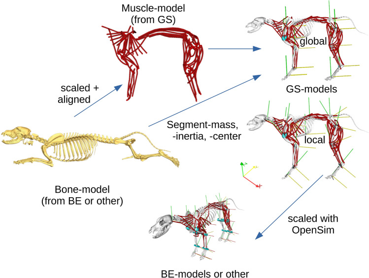
Figure 7.
Representation of the model assembly, from the bone model (yellow bones) to the muscle model (red paths) to the resulting simulation model, taking into account the transformations performed. The muscles (red) can be generated as paths closer to the real curves or just straight. Rotation around the red axis (x) represents protraction/retraction or flexion/extension, around the yellow axis (y) abduction/adduction, and around the green axis (z) axial rotation. The sub-figures were created using the software packages Amira57 and OpenSim28,29.

