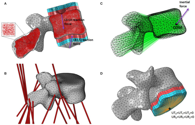
Figure 2.
Base mesoscale structural model of L4. (A) Side cut with load applicators. (B) 3D view with musculotendon actuators from the musculoskeletal model. (C) Side view with inertial load applicator. (D) 3D view with boundary condition. Cortical shell elements are shown in grey and trabecular truss elements in dark red. Wedge elements of the softer layers of the load applicators are shown in light red while the stiffer layers elements are in light blue. Truss elements connecting the nodes on the external layers of the load applicators to the joint centres where the joint reaction force is applied are shown in black. Truss elements of the inertia applicator connecting the nodes of the cortical elements to the centre of mass (COM) of the lumbar segment where the inertial force is applied are shown in green. Beam elements connecting the nodes on the external layer of the load applicator to the duplicate node at the joint centre for the boundary condition are shown in orange.

