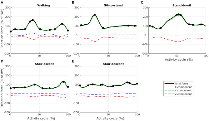
Figure 3.
Selection of load cases for L4, for five activities related to locomotion ((A) level walking, (B) standing up from a chair, (C) sitting down on a chair, (D) walking up the stairs, and (E) walking down the stairs). Total reaction force at L4–L5 joint derived from the musculoskeletal model and normalised to body weight (BW) are shown as black lines. Dots indicate the frames selected for the finite element analysis. Red, green, and blue dashed lines show X, Y, and Z components of the reaction force expressed in the vertebra coordinate system.

