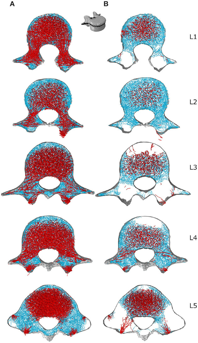
Figure 8.

Through-processes transverse (XZ plane) slices for the converged models adapted to the healthy scenario (A) and the sedentary scenario (B). In the background, cortical shell elements are shown in grey. Thicker truss elements representing the primary structure located between the superior endplate and the through-processes transverse slice are shown in red. Trabecular truss elements representing the secondary structure (with a radius of 0.1 mm) are shown in blue for a 3 mm slice. Truss elements in the dead zone (with a radius of 1 μm) are not shown for clarity.
