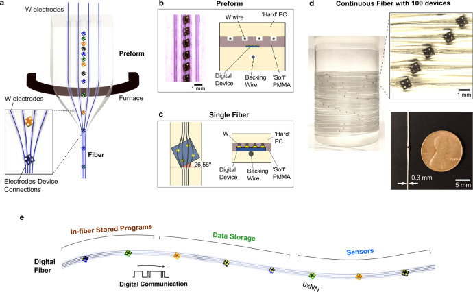
Fig. 1. Fabrication approach of digital fibres.
a Thermal drawing of the digital fibre preform by feeding conductive tungsten wires into the empty channels. At the preform level, the tungsten (W) wires are spaced far apart with a polymeric barrier separating the device and the wires. The inset shows the converging of the four tungsten (W) electrodes toward the four electrical device pads at the necking region of the preform-to-fibre transition. b (left) Optical micrograph of the rotated devices embedded within preform slots milled at a critical angle of 26.56° relative to the preform axis. (right) Cross-sectional schematic of preform, containing three layers (hard PC/soft PMMA/hard PC). The presence of the hard PC enables an inwards compression that allows W electrodes to break through the soft PMMA barrier and make contact with the device electrical pads. The backing wire is used to compress the device on the opposite side from the electrode wires and to prevent tilting of the device along the fibre length. c (left) Schematic of drawn fibre with the rotation of embedded devices preserved at the critical angle of 26.56°, allowing for the electrical pads to contact four parallel wires without shorting. Spreading of the tungsten wires at the device region is also taken into account for the wires to align with these electrical pads. (right) Cross section schematic of the digital fibre at the device region, showing electrical contacts between device and wires. d (left) Photograph of a spool containing a continuous digital fibre with 100 embedded devices. (right) Magnified optical image of the fibre array showing that the digital devices are all rotated to the critical angle with connections to wire electrodes. (bottom) Photograph showing size comparison between the fibre and a coin (penny). e Illustration of the thermally drawn digital fibre encapsulating chips of different functionalities such as memory or sensing. Each of the chips is represented by a unique and different digital address in hexadecimal format (0xNN). The four wires within the fibre serve different functions: signal line for exchanging data between in-fibre devices, clock line to regulate communications signal timing, ground line, and power line.

