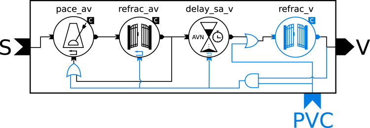
Fig. 6. Diagram of the extension of the modular conduction model with a trigger for (PVCs).
The components are the same as in Fig. 5 with additional components and connections highlighted in blue: reset inputs, second RefractoryGate (right) for the refractory period of the ventricles, two logical OR gates and one AND gate. The letters on the outside of the rectangle represent the connections of the model to the outside world: the input from the SA node (S), the output to the ventricles (V) and the trigger signal for PVCs (PVC).

