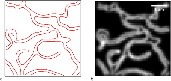
Fig. 1.
a. Reference structure used in the simulations (red lines identify where emitters are allowed to be located, including individual positions). b. Simulated widefield image of the reference structure, obtained with the procedure explained in section 3.1.

