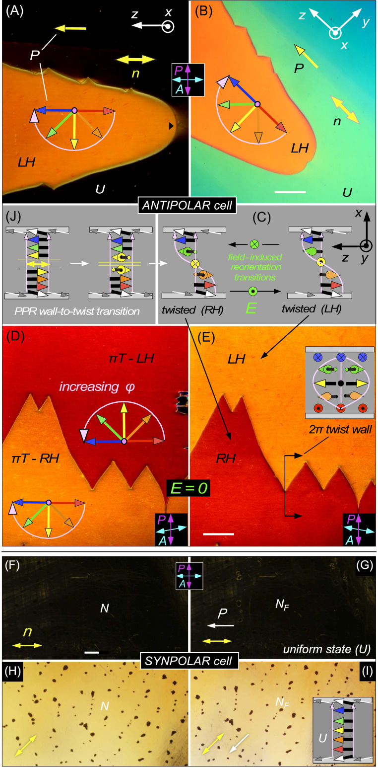
Fig. 2.
Orientational states of ANTIPOLAR and SYNPOLAR cells. Stable states in the NF phase induced by polar surface anchoring generated using unidirectional buffing, imaged using DTLM on cooling from T = 135 °C to T = 125 °C. The red-to-blue arrow sequence represents the ferroelectric polarization orientation at increasing heights in the cell (x = 0, d/4, d/2, 3d/4, d, where d = 3.5 µm in A–E and 15 µm in F–I). The pink arrows indicate the azimuthal angular trajectory of 𝜑(x) from the bottom to the top of the cell, which is also the light propagation direction. (A and B) A d = 3.5 µm ANTIPOLAR cell with a left-handed (LH) πT state (orange) growing into a uniform (U) state. The U state is dark between crossed polarizer and analyzer when n is either parallel or normal to the analyzer, but shows light green/blue birefringence when rotated (B). The color of the πT state does not depend strongly on cell orientation. (C) Schematic diagram of the LH and RH πT states. In an ANTIPOLAR cell, with the field applied, E and the white LC polarization vectors at the surfaces form a triad that is structurally chiral and changes handedness if E changes sign, implying that field reversal will tend to flip the handedness of the n,P structure. (D and E) Decrossing the analyzer lifts the optical degeneracy of the LH and RH states, revealing their chirality and optical symmetry under simultaneous mirror reflection and reversal of the decrossing angle. The LH and RH states are separated by a 2π-twist wall. (F–I) Uniform (U) NF state obtained on cooling a d = 15 µm SYNPOLAR cell from the N phase. With n parallel to the crossed analyzer, the cell is dark (F and G), showing quality, planar alignment of the director in both phases except near air bubbles (dark spots) in both phases. In the NF phase, the polarization is uniformly aligned, with no domains of opposite polarization observed anywhere in the cell. The sample is rotated through 45° in H and I. (J) Spontaneous transition of a pure polarization reversal (PPR) wall to a twisted state. In the absence of a gradient in T, the uniform director state has formed and grown in independently from each surface, making a PPR wall near the cell center. The twist deformation at the PPR wall (yellow vectors) initially costs local twist Frank energy but the system eventually lowers the energy by effecting a topological transition that converts the PPR wall into uniform director twist between the cell plates. This transition is barrier-limited. When cooling an ANTIPOLAR cell in a temperature gradient, the PPR wall forms near the warmer surface. (Scale bars: 200 µm.)

