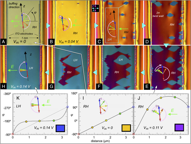
Fig. 4.
Low-field polarization reversal in an ANTIPOLAR cell of RM734 at T = 125 °C. The cell thickness is d = 3.5 μm. In-plane ITO electrodes with a 1 mm gap are used to apply an electric field E normal to the electrode edges. At the gap center, E = (VIN/L) V/mm, where VIN is the voltage applied to the electrodes and L ∼1.5 mm their effective spacing due to the thin-electrode field geometry. The buffing directions are along the z axis, which is oriented 3° from the electrode edges and therefore 93° from E. (A) Initial right-handed (RH) πT state in the absence of field. (B–H) Gradually increasing the applied voltage in the range 0 < VIN < 0.4 V distorts the RH twist state and leads to the nucleation and growth of LH twist regions. The red-to-blue arrow sequences represent the ferroelectric polarization orientation at increasing heights in the cell (x = 0, d/4, d/2, 3d/4, d). The pink arrows indicate the azimuthal angular trajectory from the bottom to the top of the cell, which is also the light propagation direction. The 3° offset between the buffing and electrode orientations breaks the mirror symmetry about E, causing the n-P couple to rotate preferentially counterclockwise in response to P x E torques (white arrow in [B]). At VIN ∼90 mV (E ∼60 mV/mm in the gap center), the LH πT state appears in several places via heterogeneous nucleation, being the field preferred state since it has P largely directed along E. The field tends to expel the LH twist to the surfaces, filling the cell center with the preferred orientation. The LT and RH πT states are separated by 2π-twist walls. The domain walls in E–H move readily in response to small increases in the applied field but the internal structure of the LH and RH states changes little in this voltage range. (I–K) Steady-state director profiles φ(x) of the LH and RH states calculated numerically by solving the field/elastic torque balance equation given in the text, assuming fixed surface orientations at φ(0) = -87° and φ(d) = 93°. (I) Uniformly twisted RH starting state in the absence of applied field. (J) Deformed RH state in presence of an E field favoring φ = ±180°. Because the buffing is not perpendicular to the applied field, and P in the starting state in (I) has a component directed opposite E, there is a net counterclockwise reorientation of P in the cell. (K) The field finally induces a transformation, shown schematically in Fig. 1E, from the RH to the LH twist state. The polarization profile, corresponding to the azimuthal angular trajectory sketched in (H), is plotted here with φ increasing downward. Insets show the calculated transmitted hue of the model twist states between crossed polarizer and analyzer.

