. 2020 Nov 16;12(1):50–70. doi: 10.1039/d0sc03715j

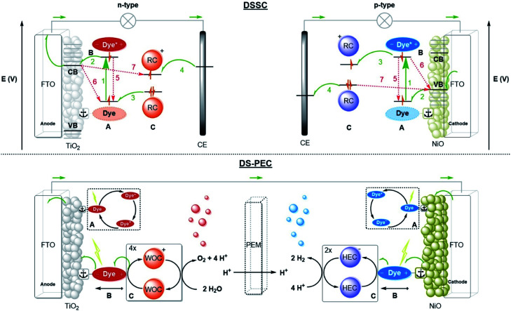
Fig. 2. Operational mode of the DSSC (top) and schematic diagram of a DS-PEC (bottom). (A) Dyes anchored on a semiconductor deposited on conducting FTO glass are excited by light. (B) The dye performs charge-separation and (C) oxidizes or reduces the redox couple (RC) in the electrolyte that delivers the charge to the counter electrode (CE) closing the circuit. For n-type the dye is excited (process 1) followed by fast electron injection into the conduction band (CB) (process 2). The dark colour represents the dyes in the depicted electron configuration. The dye is oxidatively quenched by the redox couple (RC) (process 3). The RC is then regenerated at the counter electrode (CE) (process 4). In p-type the electrons move the other way around, but the processes are equivalent to n-type. The dye is excited (process 1) after which it is reductively quenched by an electron in the valence band (VB) of the NiO. The electron of the reduced dye is transferred to the RC (process 3) after which the redox mediator is regenerated at the CE. The possible recombination pathways are depicted with red arrows. A DS-PEC performs processes (A) & (B) in a similar fashion. Process (C) is altered by substituting the RC for a redox catalyst performing reactions such as water splitting. The catalyst may be anchored to the semiconductor surface or dye as diffusion is not required. Water oxidation catalysts (WOC) oxidize water to oxygen and protons. Four oxidations are required to generate a single oxygen molecule. The hydrogen evolution catalyst (HEC) combines the electrons and protons liberated at the anode to form hydrogen gas at the cathode. Every hydrogen molecule requires two electrons from the HEC. The half reactions are often separated by a proton exchange membrane (PEM).

Fig. 2