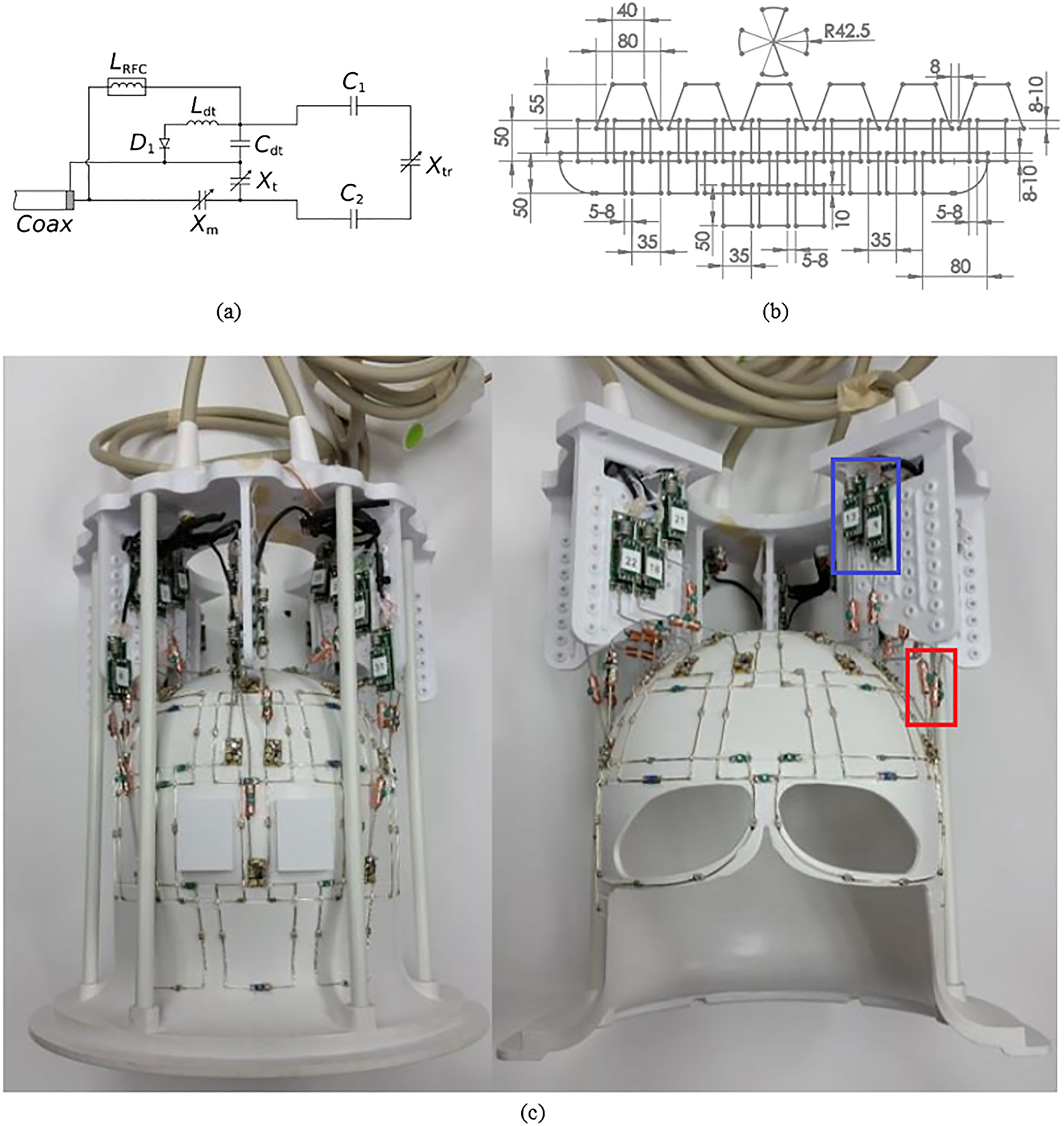
FIGURE 1.

The 10.5T 32-channel receive array. A, schematic of the feed circuit and loop element, showing the tune (Xt) and match (Xm) capacitors, the detuning trap (Ldt and Cdt), the loop element (fixed C1 and C2 capacitors and trimmer capacitor Xtr), and an RF choke (LRFC). B, Flattened layout of the coil (approximate dimensions in millimeters). C, Photograph of the coil as built (with the blue box marking the preamplifier boards and the red box marking the input cable traps)
