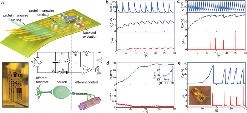
Fig. 3. Integrated wearable neuromorphic interface.
a Schematic (top) and circuit diagram (middle) of a fabricated (left) integrated wearable interface. Scale bar, 1 cm. Cm (10 µF), R1/R2/R3/R4 (20/1/100/1 kΩ), and an Op Amp (LM321) were used in the circuit. b Simulated evolution in the membrane potential (middle panel) and current (bottom panel) from the artificial neuron when receiving emulated normal (e.g., 0.3 Hz) respiratory sensing signal (top panel). c Simulated evolution in the membrane potential (middle panel) and current (bottom panel) from the artificial neuron when receiving emulated abnormal (e.g., 1 Hz) respiratory sensing signal (top panel). d Measured membrane potential (top panel) and current (bottom panel) from the artificial neuron with the sensor exposed to normal breathing. (Inset) The “stars” indicate discharging in membrane potential during breathing intervals. e Measured membrane potential (top panel) and current (bottom panel) from the artificial neuron with the sensor exposed to abnormal breathing. (Inset) The lighting of the LED (0805URC) triggered by neuronal firing.

