Abstract
Summary: We assessed the feasibility, accuracy, and safety of securing site-selective brain biopsy specimens by using a real-time CT-guided stereotactic navigation system through a mini-burr hole in the skulls of two dogs. Two beagle dogs each underwent two biopsy procedures. Our results indicated that the navigation system was accurate, safe, fast, and reliable for performing real-time brain biopsy in dogs and eliminated the need or risk of a standard-flap craniotomy.
Standard neuroimaging techniques (CT and MR imaging) provide excellent anatomic definition and the flexibility of multiplanar imaging to allow characterization of intracranial lesions, but confirmation of findings to plan therapy requires a histopathologic diagnosis. The most common biopsy localization systems combine an imaging technique with a fixed biopsy head frame (1–12). The drawbacks of these systems are extensive equipment and training, prolonged setup time, limitations that interfere with acquisition of further sequential images, head fixation, advanced computer calculations for multiple images, and acquisition of the actual biopsy specimen at a later point in time in a different location than that on the guiding image, with no real-time image confirmation of the progress of the actual procedure. More recently, frameless systems have been under investigation to reduce patient discomfort and procedure duration; however, these are used with no real-time documentation of the progress of the procedure. We herein describe the use of an accurate, real-time stereotactic biopsy prototype for needle brain biopsies in adult beagle dogs. This system allows predefinition of a specific targeting vector for accurate placement of a biopsy needle and provides an accurate and minimally invasive real-time method of obtaining brain biopsy specimens, without producing neurologic complications.
Technique
Two healthy male adult beagle dogs each underwent the same biopsy procedure twice, 10 weeks and 3 weeks apart, with a neurologic examination performed 1 day before every biopsy procedure and daily for 1 week after biopsy. The results of the neurologic examination were graded, and a total score was calculated from a maximum of 80 points. The neurologic evaluation included a general gait analysis examination (14 points), cranial nerve examination (34 points), postural reaction examination (12 points), and spinal reflex examination (20 points).
Before undergoing biopsy, each dog was premedicated with acepromazine (0.2 mg/kg intramuscularly administered) and butorphanol (0.15 mg/kg) before receiving general anesthesia with propofol (3 mg/kg intravenously administered) that was maintained with 2% to 3% isoflurane in 100% oxygen. Lactated Ringer’s solution was intravenously administered at a rate of 5 mL/kg/h. The dogs were positioned in the CT scanner, and their heads were stabilized with a customized head frame consisting of vertical and horizontal metal rods fixed in a wooden frame.
One dog was killed after a 2-week period of recovery after the second biopsy (beagle 1), whereas one dog remained alive (beagle 2). A necropsy was performed in the first case with complete histologic analysis of the brain, focusing on the areas from which the tissue samples were taken. Representative formalin-fixed brain tissue samples were paraffin-embedded, sectioned, and stained with hematoxylin and eosin for histologic examination.
All images were obtained by using a fourth-generation helical CT scanner, the Picker PQS (Cleveland, OH). Routine image parameters and techniques included a 512 × 512 matrix and a 20-cm field of view; 2- to 3-mm-thick sections were acquired by using a standard brain algorithm.
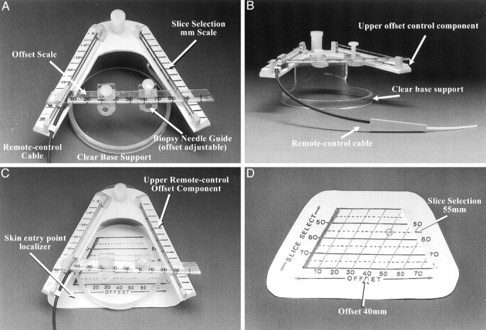
A simple mechanical device, the Utopix 3D Vector Guide (Utopix LLC, Columbus, OH), was used to precisely define the two points of the optimal targeting vector by using a single image and its 3D radiopaque image-conspicuous V-shaped pattern coordinate system to define the target trajectory before the procedure began, with no computer calculations or electronic components. The device has three main components, each of which has a patented millimeter-scaled pattern: 1) a nonsterile skin entry point locator to define the entry point (Fig 1D), 2) a sterile skin entry point localizer to continuously monitor entry point location during the procedure, and 3) an upper device level with a remote-controlled pattern on a sterile drape and base ring assembly to determine a second vector definition point in space approximately 5 cm above the subject (Fig 1A and B). To maintain geometric integrity, the patterns must be placed parallel to the image section plane.
Fig 1.

Components of the stereotactic CT navigator.
A, View of the upper portion of the device, seen from above (operator’s perspective). The V pattern is at a 53° angle. The measured millimeter distance between the two V limbs (slice-select) is printed on a scale (left), and a 5-mm scaled pattern grid is seen parallel to the section plane location (Slice Selection mm Scale). A linear transparent millimeter scale and needle support offset scale are actuated by the remote control cable. A millimeter scale on the moving needle guide is used to define the offset. Two small needle supports can be used to hold the needle at a precise point. The upper V pattern is supported on an elevated circular clear plastic support ring.
B, View of the upper level device V pattern. The remote control cable, clear base support, and upper offset scale control component are labeled.
C, View of the device from above (operator’s view), with the skin entry point localizer seen beneath the upper remote control offset scale component.
D, View of a nonsterile opaque skin entry point locator pattern.
The patented device pattern incorporated an inverted truncated V-shaped image-conspicuous (radiopaque) scaled grid with an image-conspicuous broadband reference line incorporated on the pattern adjacent to and to the left of the left V pattern limb (to differentiate the left side of the pattern from the right and avoid confusion regarding left-right orientation) (Fig 1D). The measured millimeter distances on the image translate to identical measurements on the device patterns and are used to define the two target vector determinant points, one on the subject’s skin and one above it, each of which is expressed in standard point coordinate form (eg, slice-select, offset coordinate). The slice-select coordinate, measured on the image as the millimeter distance between the two pattern limb dots, is the true image section plane location on the pattern on the patient, and the second point coordinate, the offset, is the millimeter distance measured on the image between the left (zero reference) pattern limb to the point of intersection with the desired targeting vector. These two simple measurements on the image define millimeter-precise points in real space in 3D by using the pattern and real-time image information only. The upper device component also incorporates a moveable, remote-controlled, image-conspicuous V reference millimeter-scaled pattern grid with a needle support. A remote-control cable (consisting of a plastic-wire catheter-drive mechanism) allows precise real-time positioning of the reference millimeter pattern with regard to the image section plane and the needle (Fig 1B). The complete biopsy system, including both the sterile skin-entry point localizer and the upper level vector remote-controlled pattern scale with base ring, is shown in Figure 1C.
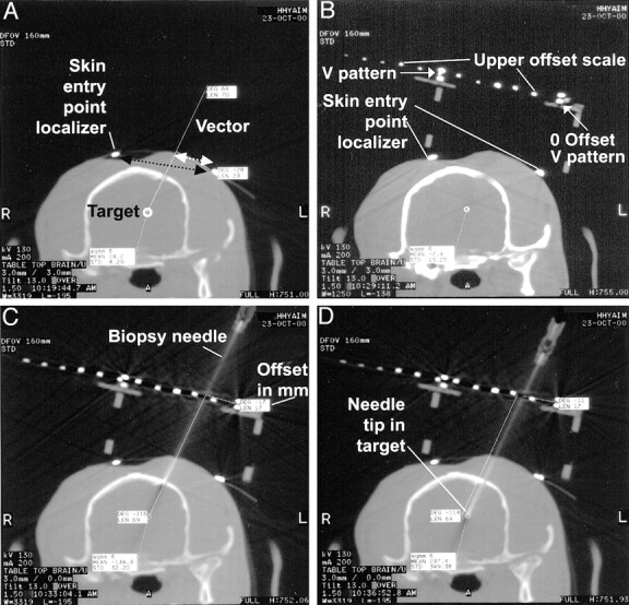
The dogs were placed under general anesthesia with the head in a specially designed frame, and a series of CT scans were acquired to locate the target, the chosen vector, and the skin entry point, by using a nonsterile skin entry point localizer pattern. The skin over the brain area of interest was routinely surgically prepped and draped, and the sterile self-adhesive skin entry point pattern localizer was placed over the area of interest. The skin entry point and an ideal targeting vector (trajectory) were drawn on the CT monitor (Fig 2A), and the section location coordinate (slice-select) and offset measurement coordinate (offset) were measured on the image and transposed to the skin entry point pattern, marking the skin at that point. A skin incision was made at the chosen skin entry point and advanced into the muscle to the bone, after which a short cylindrical metal guide with a handle was used to stabilize the drill at the chosen mini-burr hole site. A hand drill with a 3-mm bit and an adjustable depth stop was used to drill a hole in the skull through the metal drill guide in a direction consistent with that of the desired vector, and an 8F angiographic catheter guide or a metal guide was then inserted through the soft tissues to the mini-burr hole site. This guide obviated the need for a standard large muscle flap resection to keep the path to the target free of debris. The upper remote control device component was then attached to the dog’s head in a position corresponding to the planned vector and rotated parallel to the image section plane. An image was acquired through the target that included the device components, the desired optimal targeting vector was redrawn on the monitor, and measurements were made on the image of the slice-select and offset coordinates on the upper device pattern (Fig 2B). A twist-cutting brain biopsy needle was aligned on the upper device pattern at the chosen slice-select, offset location point, held in place with a needle guide clip, and advanced to the drill hole at the entry point on the skull. A vector confirmation image was obtained to confirm the trajectory and measure the depth to the target from the needle tip. If any minor adjustment in positioning were indicated, it could be measured on the pattern grids and corrected as necessary. The needle was advanced the measured depth distance to the target, and another image was used to confirm correct needle position, after which the brain biopsy was completed. The device was removed from the procedural field, the skin incision was closed in a routine manner, and a follow-up image was obtained to exclude any complication. The dogs recovered immediately after the biopsy, and dexamethasone sodium phosphate (0.1 mg/kg) was intravenously administered after the procedure for treatment of any cerebral edema. The average procedure time was 2.5 hours, and representative brain samples were successfully obtained all four times. The dogs did not have neurologic deficits beyond 1 week after biopsy (with two of the procedures, the dogs did not show any neurologic deficit immediately after the biopsy; with one of the procedures, the dog had moderate deficits for several days; and with one of the procedures, the other dog had mild deficits for 1 day).
Fig 2.

CT scans of a navigator-directed brain biopsy.
A, Two-millimeter-thick CT section centered at the target section plane location. The ideal chosen targeting vector is drawn on the computer monitor. In this case, the procedural goal was to direct the needle to the lateral superior margin of the lateral ventricle (not shown). The two small hyperattenuated dots shown on the scalp are the V pattern limbs of the skin entry point localizer. The millimeter distance measured on the image between these two points (black dotted arrow) is used to define the slice-select location. The measured distance from the zero reference pattern limb dot to the vector drawn on the image (white dotted arrow) is the offset distance.
B, Device upper level V pattern in place. The small mini-burr hole has already been drilled and is centered on the planned vector skin entry point. The two limbs of the skin entry point pattern are labeled. The moveable upper level device offset scale has small dots for direct millimeter visualization. In this case, the measured distance between the two V limbs is 60 mm because the distance between the two V limbs is six dots (10 mm/dot) on the upper scale. The chosen targeting vector is drawn on the image, and the offset is 17 mm; the needle is supported at this position.
C, Needle placed on the surface of the brain. This offset accurately aligns the needle with the chosen vector. The needle is advanced the measured depth distance.
D, Needle in the target point, precisely along the planned vector (see A).
Discussion
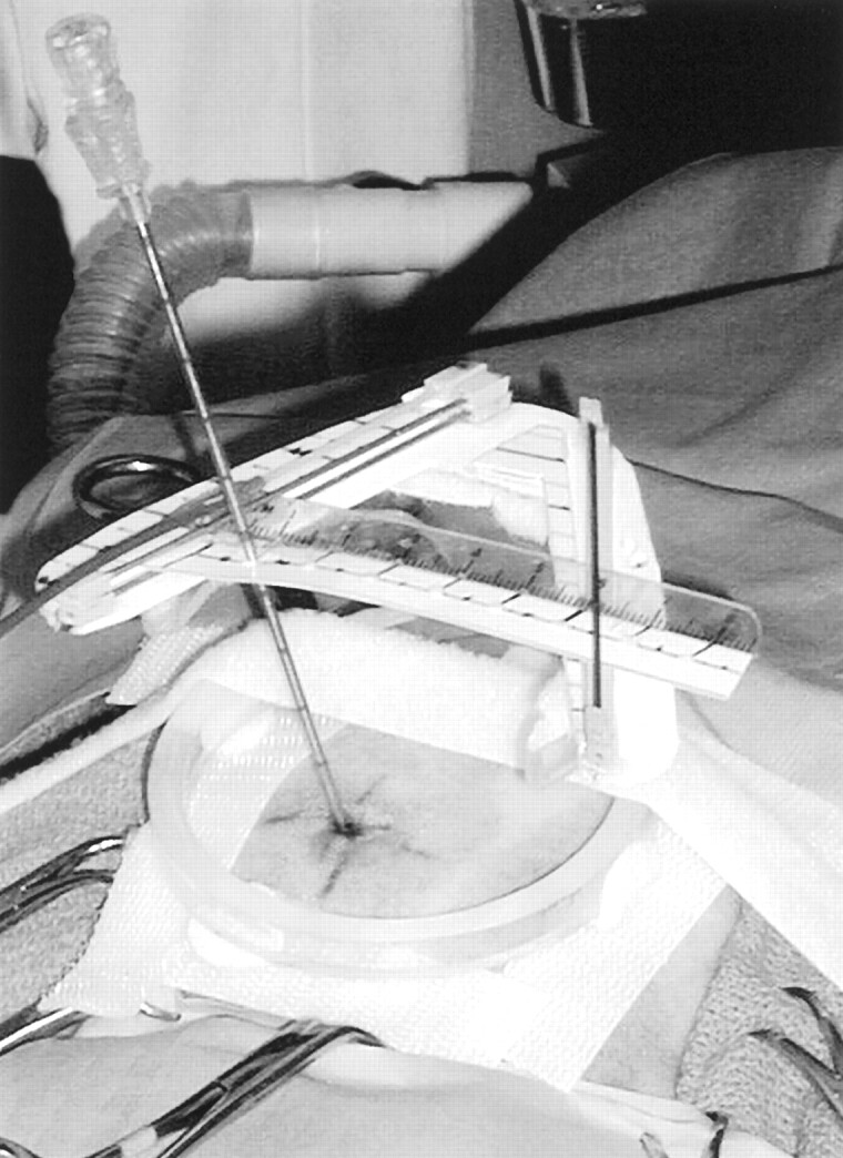
The results herein show that the real-time CT-guided stereotactic navigator can be used to obtain accurate, safe, and site-selective brain biopsy specimens through a mini-burr hole in dogs. The system described has several advantages compared with other stereotactic brain biopsy systems. Most of these current methodologies are very complex, expensive, and time-consuming, and may operate without the advantage of real-time imaging, usually in a surgical-suite environment. The 3D Vector Guide uses a different strategy; it can be viewed as a “flexible frame” system that simultaneously establishes the target trajectory and supports the needle during the biopsy procedure (Fig. 3). Because the system is small enough to be completely included in a small field of view, very high resolution is possible and image distortions are minimized.
Fig 3.

Photograph of the actual needle biopsy setup shows the needle entering the scalp at the previously determined and marked skin entry point. It is seen supported through the upper level needle guide, held along the upper offset scale at the correct location, to assure proper vector alignment. The remote control cable can be used to precisely position the needle in the image section plane along the chosen targeting vector.
The device has several advantages over commonly used systems. First, the exact biopsy vector and needle alignment can be monitored, controlled, and corrected at any point during the biopsy procedure; it is therefore not imperative that the patient’s skull be totally fixed or that that the biopsy device be screwed to the patient’s skull. Second, this biopsy method does not require a standard flap craniotomy but operates through a “mini” burr hole craniectomy (3 mm), allowing minimized technical support, including a reduction in required instrumentation and personnel compared with those needed for a standard flap craniotomy. For these reasons, the device system is much less expensive than other biopsy systems in use.
Conversely, the minimally invasive approach is also responsible for the major disadvantage of this procedure. The biopsy area cannot be visualized directly through a mini-burr hole, and therefore, possible hemorrhage cannot be immediately stopped. In addition, the small drill hole in the skull does not allow for brain expansion caused by procedure-related brain edema, which can produce the potential risk of brain herniation. However, neither of the dogs in this study developed obvious hemorrhage, as determined by follow-up CT or any significant clinical sign of progressive cerebral edema.
Conclusion
Our results indicated that this stereotactic CT navigator system is an accurate, safe, fast, reliable, and inexpensive method for real-time brain biopsy in dogs. This technique dramatically simplifies the surgical approach and procedure by avoiding the use of a standard muscle flap resection and burr hole, which can significantly reduce patient recovery time. All these features make the device a viable and ideal system to use in the clinical setting. Potential applications of the device include cyst drainage, ventriculostomy, and targeted delivery of drug, gene, and chemotherapy agents.
References
- 1.Carol M, Smith D, Love L. Experiences with Pelorus stereotactic system. Appl Neurophysiol 1987;50:133–135. [DOI] [PubMed] [Google Scholar]
- 2.Koblik PD, LeCouteur RA, Higgins RJ, et al. Modification and application of a Pelorus Mark III stereotactic system for CT-guided brain biopsy in 50 dogs. Vet Radiol Ultrasound 1999;40:424–433. [DOI] [PubMed] [Google Scholar]
- 3.Hall WA, Martin AJ, Liu H, Nussbaum ES, Maxwell RE, Truwitt CL. Brain biopsy using high-field strength interventional magnetic resonance imaging. Neurosurgery 1999;44:807–814. [DOI] [PubMed] [Google Scholar]
- 4.Moriarty TM, Quinones-Hinojosa A, Larson PS, et al. Frameless stereotactic neurosurgery using intraoperative magnetic resonance imaging: stereotactic brain biopsy. Neurosurgery 2000;47:1138–1146. [DOI] [PubMed] [Google Scholar]
- 5.Levivier M, Goldman S, Pirotte B, et al. Diagnostic yield of stereotactic brain biopsy guided by positron emission tomography with [18F]fluorodeoxyglucose. J Neurosurg 1995;82:445–452. [DOI] [PubMed] [Google Scholar]
- 6.Pirotte B, Goldman S, Bidaut LM, et al. Use of positron emission tomography (PET) in stereotactic conditions for brain biopsies. Acta Neurochir (Wien) 1995;134:79–82. [DOI] [PubMed] [Google Scholar]
- 7.Germano IM, Villalobos H, Silver A, Post KD. Clinical use of the optical digitizer for intracranial neuronavigation. Neurosurgery 1999;45:261–269. [DOI] [PubMed] [Google Scholar]
- 8.Chakeres DW. United States patent 5, 690, 108. Real-Time/Space Stereotactic Navigator,1997. .
- 9.Koblik PD, LeCouteur RA, Higgins RJ, et al. CT-guided brain biopsy using a modified Pelorus Mark III stereotactic system: experience with 50 dogs. Vet Radiol Ultrasound 1999;40:434–440. [DOI] [PubMed] [Google Scholar]
- 10.Laitinen LV, Liliequist B, Fagerlund M, Eriksson AT. An adapter for computed tomography-guided stereotaxis. Surg Neurol 1985;32:559–566. [Google Scholar]
- 11.Bernays, RL, Kollias, SS, Khan, N, Romanowski B, Yonekawa Y. A new artifact-free device for frameless, magnetic resonance imaging-guided stereotactic procedures. Neurosurgery 2000;46:112–117. [PubMed] [Google Scholar]
- 12.Barnett, GH, Miller, DW, Weisenberger J Frameless stereotaxy with scalp-applied fiducial markers for brain biopsy procedures: experiences in 218 cases. J Neurosurg 1999;91:569–576. [DOI] [PubMed] [Google Scholar]


