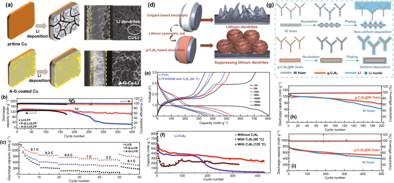
Fig. 25.
a Schematic illustration and SEM images of the cross-sectional view of Li deposition on pristine Cu and A-G-Cu electrodes before cycling and after depositing 5 mAh cm−2 of Li. b Cycle performance of the Li//LFP full cells with Li, P-G-Li, and A-G-Li. c Rate capability and of the Li//S full cells with Li, P-G-Li, and A-G-Li. Reproduced with permission from Ref. [151]. d Scheme of Li dendrite growth and inhibition depending on Li symmetric cells with g-C3N4 or without addition. e Galvanostatic charge/discharge curves of Li/FeS2 cell based on LiTFSI-DGM-C3N4 electrolyte of at 0.1C in a voltage range of 1—3 V. f Cycling performance of LiTFSI-DGM-C3N4-based Li/FeS2 cell (red circles) and its comparison with Li/LiTFSI-DGM/FeS2 cell. Reproduced with permission from Ref. [152]. g Schematic of the Li nucleation and plating process on Ni foam and g-C3N4@Ni foam. h Discharge capacity and CE of Li@g-C3N4@Ni foam|LiCoO2 and Li@Ni foam|LiCoO2 cells at 1.0 C. i Discharge capacity and CE of Li@g-C3N4@Ni foam|S and Li@Ni foam|S cells at 1.0 C. Reproduced with permission from Ref. [153]. Copyright permissions from American Chemical Society and Wiley–VCH. (Color figure online)

