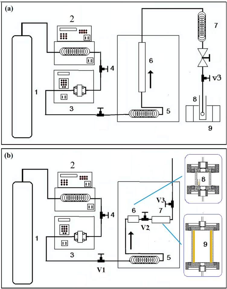
Fig. 2.
a Schematic diagram of supercritical fluid extractor including: (1) CO2 cylinder, (2) chiller, (3) syringe pump, (4) back-pressure valve, (5) heat exchanger, (6) extraction vessel, (7) restrictor, (8) collection vessel and (9) ice bath. b Schematic diagram of supercritical fluid precipitation apparatus: (1) CO2 cylinder, (2) chiller, (3) syringe pump, (4) back-pressure valve, (5) heat exchanger, (6) equilibration vessel, (7) precipitation vessel, (8) polyethylene vial for loading of sample and (9) collector (mica sheet)

