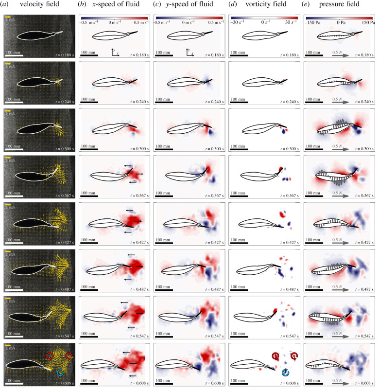
Figure 4.
Flow and pressure patterns during acceleration. Representative example of an acceleration manoeuvre at 45% duty cycle (5.9 Hz tail beat frequency). The columns show (a) velocity fields, the (b) axial and (c) lateral components of the velocity field, (d) the vorticity field and (e) the calculated pressure field including the distributed interaction forces (purple arrows) along the robot's length. Each row illustrates the different fields at the same time instance, which is displayed in the lower right corner of each panel. Circular arrows in the bottom row vorticity field panel indicate the reverse Kármán vortex street. Similar analyses for the other duty cycles tested are presented in the electronic supplementary material. (Online version in colour.)

