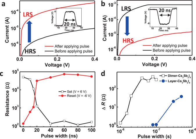
Fig. 4. Switching speed of HP RSM.
I–V characteristics of dimer-Cs3Sb2I9 RSM before and after application of (a) set pulse (6 V, 20 ns) and (b) reset pulse (−6 V, 20 ns). c Resistance changes of dimer-Cs3Sb2I9 RSM device with different pulse widths. Amplitudes of applied voltage pulses are fixed for set (6 V) and reset (−6 V) processes. d Resistance changes of dimer-Cs3Sb2I9 RSM and layer-Cs3Sb2I9 RSM devices by application of set pulses (6 V) with different pulse widths. ΔR is defined as the ratio between initial resistance and changed resistance after pulse application.

