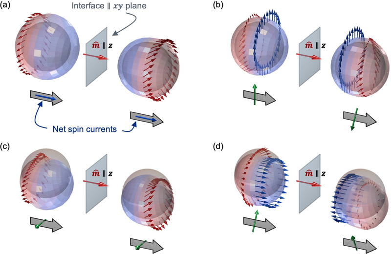
FIG. 12.
Plots depicting the nonequilibrium distribution functions gα(0±, k) in the presence of interfacial spin-orbit scattering. Each picture illustrates the physics captured by a single matrix element in the matrices defined in Eq. 33 or Eq. 38. The interfacial exchange field (red arrow) points out-of-plane (along z). The gray sphere represents the equilibrium Fermi surface. The colored surfaces represent the nonequilibrium perturbation to the Fermi surface, given by the charge distribution gc(0±, k). The arrows depict the spin distribution function gi(0±, k) for i ∈ [x, y, z] for particular contours over the Fermi surface (which have constant polar scattering angle). Blue and red regions represent the incoming and outgoing (scattered) carriers respectively. The net spin current at z = 0± is shown below the distribution functions, where the block arrows denote spin flow (always out-of-plane) and the tubular arrows denote spin direction. Note that we use transverse and longitudinal to denote spin directions relative to the interfacial exchange field. (a) Scenario where the incident carriers have two different charge accumulations but no spin accumulation. Regardless, the scattered carriers are spin polarized from their interaction with the interfacial exchange and spin-orbit fields. The net spin currents after scattering have longitudinal spin directions and are conserved across the interface. (b) Scenario where the incident carriers have two different transverse spin accumulations. The net spin currents after scattering also have transverse spin directions but are rotated relative to the spin accumulation and not conserved across the interface. (c) Scenario where two different in-plane charge currents flow at z = 0±, indicated by differing shifts the Fermi surface. The scattered carriers become spin polarized and the net out-of-plane spin currents have transverse spin direction. (d) Scenario where two different in-plane, longitudinal spin currents flow at z = 0±. The net out-of-plane spin currents have transverse spin direction and are not conserved across the interface.

