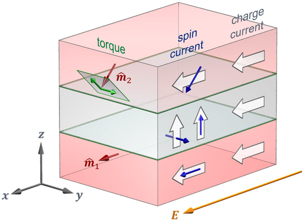
FIG. 7.
Magnetic trilayer and in-plane transport. The top and bottom ferromagnetic layers are separated by a non-magnetic layer. In each layer, the current flows along the electric field, where flow directions are given as block arrows. In the ferromagnetic layers, the spin currents shown here flow along the charge currents with spins aligned with the magnetization (indicated by red arrows). Note that for spin currents, block arrows give flow direction and blue arrows give spin direction. Green arrows indicate the two components of the torque on the magnetization. In the non-magnetic layer, spin currents originating in the lower ferromagnetic layers and flowing out-of-plane have spin directions along both and (other contributions to the spin current are not shown). The spin currents with y-spin direction can arise from the spin Hall effect in any layer or through the spin-orbit filtering effect at interfaces. The spin currents with z-spin direction are not allowed by symmetry in bulk nonmagnets; these spin currents can only arise in the ferromagnetic layers through various processes or at the interfaces through the spin-orbit precession effect. Spin transfer torques arising from the spin currents with z-spin direction could switch ferromagnetic layers with perpendicular magnetic anisotropy, suggesting applications of possible technological interest.

