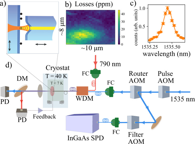
Fig. 1. Description of the experiment.
a Schematic drawing of the tunable fiber-based microcavity. The fiber mirror can be moved in 3D, allowing us to set the length of the cavity and locate a nanoparticle inside the cavity. b Map of scattering loss introduced by a single nanoparticle when scanning the cavity mode across it. c Measurement of the inhomogeneous line of the 4I15/2–4I13/2 transition. The solid line is a Gaussian fit, yielding a full-width-half-maximum linewidth of 15(2) GHz (error bars represent one standard deviation). d The optical setup is described in more detail in the SI. In summary, a 1535-nm laser is used to excite the ions and a 790-nm laser to stabilize the length of the cavity. The two lasers are combined using a wavelength division multiplexer (WDM). A set of acousto-optic modulators (AOM) are used to create pulses from the CW excitation laser, to route the excitation light to the cavity and the cavity photons to the detector, and to suppress the excitation light to the single-photon detector (SPD) by 60 dB (InGaAs, detection efficiency 10%) during excitation. DM is a 780/1535 nm dichroic mirror, PD are continuous avalanche photo-diodes (APD) for cavity length stabilization and transmission monitoring.

