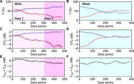
Fig. 4. Demonstration of iterative optimization scheme.

(A to F) Transmission at top and bottom MMI outputs simultaneously detected using dual-fiber output under conditions of iterative optimization (A, C, and E) and device reset (B, D, and F) at 750-nm pixel pitch. Only results for accepted pixels are shown. Panels represent raw signal intensities (A and B), log transmission normalized to the value of the unperturbed device (C and D), and the sum of top and bottom outputs normalized to the unperturbed device (E and F) showing a 0.50-dB excess loss of the patterned device. Full videos of write/reset are shown in the Supplementary Materials.
