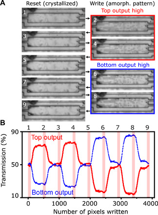
Fig. 5. Reconfigurable optical routing between two outputs within an MMI.

(A) Optical images of an MMI in the reset state (1, 3, 5, 7, and 9) and for patterns that are optimized for the top (2 and 4) and bottom outputs (6 and 8). Emerging dark areas at edges of device after reset (3, 5, 7, and 9) correspond to irreversible damage. (B) Continuous transmission ratio for the top (red) and bottom (blue) outputs of the MMI during the pattern writing and rewriting; numbers correspond to maps in (A).
